David Notebook: Difference between revisions
| (36 intermediate revisions by the same user not shown) | |||
| Line 1: | Line 1: | ||
==Things to Do/Check== |
==Things to Do/Check== |
||
*Upload power meter data....meh |
|||
*Measure beam size for isolator intensity limit |
|||
*circularly polarize everything for preferential anti-stokes generation |
|||
*finish mode matching python program and upload |
|||
*mount the power strip |
|||
==Questions for Deniz== |
|||
*<strike> Check the RF generator with the giant screen--is it actually broken and putting sidebands on or is it set to modulate the primary signal? </strike> '''not broken''' |
|||
*Do photons from a laser with a broad linewidth have a larger an uncertainty in energy, or is it just that that laser contains a wider energy distribution? |
|||
*Upload power meter data |
|||
== |
==Daily Log== |
||
'''5/10/2016''' Swapping back to short cavity. Long cavity is at 46x5. Walk mirrors at 40x3, 39x7 (pedestal location). 250 mm lens at 39x4, 700mm lens at 41x23. Pickoff at 35x3 (pedestal). Other mirrors at 31x3, 31x23. |
|||
*What is the limiting factor in the pump/stokes power we input. Why only 20W--only about 12W for stokes makes it to the cavity. |
|||
*When under vacuum, does it matter whether the cavity is cooled? Surely alignment will be slightly different, but just for getting the lock working well it would be easier to not have to add nitrogen all the time and to not have the cavity slowly warming up. '''No in principle, but it would probably change cavity mirror couplings and I don't want to have to adjust those and then change them back''' |
|||
'''12/16/15''' |
|||
*What's with the noise on the locking signal and DC error? Is that a problem? '''Fixed it--RF generator problem''' |
|||
Swapping back to the long cavity. Short cavity showed a lot of success: 10e-6 CW efficiency, 10e-4 when ramping. Mode matching for 1064 27 cm cavity is: Cavity at 57x2 (0,0 is corner near the computer, cavity position is marked by closest screw to 0,0 holding it down). Walk mirrors at 50,3.5 and 49,7. 250mm lens at 45,4 700mm lens at 32,18 500mm at 47,23. |
|||
*How much power do we typically transmit from 1555 when under vacuum? '''1W absolute best. 700-800 mW is pretty good''' |
|||
*Why do the locks drop in power--it doesn't usually lose a lock all of a sudden, but it will continuously decrease more or less (way more rapidly with the 1555) until no more power is being transmitted? |
|||
* Do we need integral and differential gain? Isn't error signal linear? |
|||
'''11/9/15''' |
|||
*Thoughts about why adjusting the phase delay line didn't seem to produce much effect on the error signal? '''Who knows. Ask Josh. This could be important, we should try to figure it out''' |
|||
The bright flashes turned out to just be from the ramp peaks greatly expanding when the ramp was slowed down all the way--effectively the duty cycle was higher without the peak efficiency being any more. We've abandoned the two photon experiment again for now. There's nothing guaranteed the independent and generated 1555 will be in phase so maybe there's just always a lot of interference? |
|||
We got lower finesse mirrors from ECI. They came out to be around 3500 finesse and seem very promising so far. Locking is way easier, although the efficiency is still around 10e-6 for 807 generation. The linewidth when locking actually broadens some to about 0.5 MHz so we still need to figure that out. The exciting part though is that the peak efficiency is around 10e-4 when ramping! We're working on optimizing the locking performance and increasing the pressure to a more optimal place. 8 atm should be ideal due to broadening/narrowing effects. I ordered a new regulator that could handle that but am still having problem and haven't seen anything good yet. |
|||
'''9/25/15''' |
|||
We got our vacuum chamber and have the 10 cm cavity ready, but haven't set it up yet. We've looked more into the efficiency calculations and it actually seems like huge gains might come from using lower finesse mirrors--somewhat counter-intuitive. The theory breaks down a little in some of these parameter spaces (for instance getting more than 100% transmitted power), but it does suggest that lower finesse could help a lot. It's a difficult problem since the optimal finesse depends on the intra-cavity intensities, which in turn depends on the locking performance and the finesse. After more calculations and investigations we decided ~5000 at both pump and stokes would be a good balance and so we've ordered those. Calculation and mirror purchase details coming soon. Meanwhile, we've been working on the Ti:Sapph. We have all the mirrors and parts, but no luck yet aligning it. We'll right up a procedure once we figure out the best way to do it. |
|||
With the Raman cavity, we're still using the 27 cm setup and have gotten the 1555 beam going again. We've decided that locking both beams for the 2 photon experiment might be too hard right now, but we've discovered that we can get 1555 generation from 1064 (and then 807) just from ramping slowly. This suggested we might be able to do the 2 photon experiment just by ramping, which is a lot easier. It seems like it might have worked! I tuned the 2 lasers to approximately the right frequency separation, ramped the cavity and overlapped the 1555 and 1064 peaks on the scope using a combination of laser piezos and cavity piezos. The fact that both beams are aligned to the cavity guarantees spatial overlap. With a free spectral range of ~550 MHz, we'd expect only one peak overlap would work, since the transition linewidth is ~600 MHz. So I looked with an IR viewer where 807 should appear from a prism and tried overlapping different peaks. One combination gave bright flashes of light as the peaks moved back and forth over each other! Unfortunatenly I haven't been able to repeat this yet after a couple weeks of trying. We're still trying to figure out what might be different, but we'll all ready to measure the peak power when it happens. |
|||
Locking is working better than it used to. It's very helpful to look at the servo output from the box. If it doesn't go to 0 when locking, then the aux output (piezo) is most likely railed. So finding a locking area that locks around 0 is very useful. It also turned out that one of the boxes was broken--the servo output sat at 10V even when in "unlock", which basically meant that the laser current and cavity piezo were trying to drive the resonance to two different locations. We sent it back to Vescent and both boxes are working now. |
|||
'''6/29/15''' |
|||
I got the mode-matching working on that cavity. The cavity was slightly too long causing it to be unstable. I added a few O-rings, which pushed it into the stable region and then mode-matching was easy. Profiling the beam is a bit of a pain though--you can't just turn down the amplifier power with the beam cube because we'll get only the "bad" polarization which is pretty much in the 1,1 mode. Instead you have to send in mostly full power (which requires having it mostly aligned to the cavity) and then use a pick-off to look at a small portion of the beam. Locking worked reasonably well, but at .1 and .3 atm of pressure I saw no stokes generation--surprising, but we aren't cooling the cavity this time. In a previous paper we put out though we had plenty of stokes power at these pressures with no cooling in a similar cavity. I'm a little concerned and we wanted to look at much higher pressures to see what would happen, but we ran out deuterium and that's taken a few weeks to get in. Hopefully though we'll find the pressure threshold is just a little higher than before or maybe the gas was contaminated somehow and it just needs a fresh batch of deuterium. The gas should be in this week and then we'll know. |
|||
I've been working on more detailed calculations for the mixing efficiency of a cavity redesign--[[File:Modulation_Efficiency.zip|here's some code and generated plots]]. Current limitations of this calculation are that we assume constant intensity inside the cavity (i.e. the waist is very close to the spotsize on the mirrors--this is not a bad assumption for the geometries we're interested in since these tend to be more stable, but could be improved. It's not good for longer cavities especially. This could be corrected by doing some sort of total integrated intensity like in the previous entry). Additionally, the mode-overlap factor between the pump and the stokes and a potentially separate mixing beam is only valid at short cavity lengths (this term should depend on cavity length but we just use a constant multiplicative factor for all lengths). We also have limited knowledge of how locking performance will change with pressure and cavity length--the most we do is in one set of plots just introduce a multiplicative factor for the laser linewidth and cavity linewidth overlap. |
|||
The results still suggest a shorter cavity is probably the way to go, but it's unclear how much improvement we'll get. It seems unlikely to be a huge change though--the mixing efficiency scaling--(pressure*length)^2*Pump_intensity*Stokes_intensity--is misleading since increasing the pump power won't linearly increase the pump or stokes intensity and increasing length causes the intensities to drop as does pressure. So the efficiency changes from most of those terms scales more like a square root rather than the square like we hoped. |
|||
But we're moving ahead with it. I'm in the process or ordering a 10 inch vacuum chamber in which we'll probably mount a 10 cm cavity and see what happens to us. |
|||
'''6/3/15''' |
|||
Ok, so here's the deal in more detail. A couple weeks ago I started trying to modulate the HeNe instead of the orange laser, since it's single frequency and easier to detect. It's also comparably low power with about 0.5 mW inside the cavity compared to the 3 mW of the orange laser (but inferior spatial mode) Also since it's CW, I could safely look for the modulated green light. I was hoping to put some sort of bound on what would be detectable since I hadn't seen a hint of single from the modulated orange laser yet. I got the HeNe well mode matched to the cavity and got it polarized correctly (borrowing a beamcube from Nick and just rotating the HeNe barrel). After some work I was able to see green after a grating and iris and some interference filters. I'm pretty confident it was nearly maximized since it was well overlaped with the 780 beam, and that is relatively easy to optimize since I can get a large signal from the modulated beam. I wasn't able to detect an actual signal from the modulated HeNe light though despite trying a few different methods. Some rough calculations showed the noise on the lock-in amplifier was about 10 times as large as the signal I'd expect from the HeNe. That suggests it's unlikely we'll be able to see a modulated signal from the orange laser. Even if we could, we wouldn't be able to bin the power into more than a few wavelength groups, so it wouldn't really do what we wanted. |
|||
All this led us to decide it was time for a cavity redesign, since <math>10^{-6}</math> seems about the best efficiency we're able to get with the current one. That's just too low for most applications and measurements. The modulation efficiency is proportional to the <math>(P*I*L)^2</math>, with P as gas pressure, I as pump intensity and L as cavity length. Some rough calculations of the I<math>^2</math> suggest a shorter cavity might help. See result [https://wiki.physics.wisc.edu/yavuz/images/5/5e/Coherence.png here] and code [https://wiki.physics.wisc.edu/yavuz/images/0/00/Raman_cavity.zip here]. The plot is the total integrated intensity (both radial and longitudinal) of the pump beam. It assumes we get the same lock efficiency and stay at the same pressure of gas. The dots show the proposed change from our current cavity (L=.75, ROC=1) to the new cavity (L=.27, ROC=.3). Note though that this doesn't account for the cavity length factor. Including this factor, the plot looks like [https://wiki.physics.wisc.edu/yavuz/images/d/d3/Coherence-length.png this]. So actually going to a shorter cavity might hurt us slightly in the overall intensity-length factor. But the changes aren't very big. What we're really hoping is that the lock-performance will be substantially better with a shorter cavity. Right now, with about 12 Watts of incident power, we only get about 200mW out under vacuum and about a couple mW out with gas. A shorter cavity might be much easier to lock to and the performance increase could more than overcome the decrease in the intensity-length factor. We could then operate at higher pressure as well, which could greatly increase our efficiency. |
|||
We're not quite sure if or how well this would work, so before designing a new cavity we're trying out an old one we had (L=.27 with mirror radius of curvature=.3) |
|||
So that's where I'm at now. I've got the new cavity in but have been having a bit of trouble with the mode matching. It seems doable though and I'm not going to worry about the mode-matching being perfect (it probably wasn't with the old cavity). I just want to see if there's a big difference in lock-performance or not. |
|||
'''5/28/15''' |
|||
Changing out the old Raman cavity! More to come, just recording it's position here. From the corner of the table near the computer, the corner of the cavity (nearest the computer) is 45 by 6 holes away. (i.e. the corner is 0x0) |
|||
Also need to move the walking mirrors for mode-matching purposes. The Dichroic was at 36x7 and the other is at 36x3.5. The pickoff is at 41x7, and the prism is at 41x10 |
|||
'''5/18/15''' |
|||
Nick wants to borrow a vescent setup and so I'm gonna do him a solid and loan it out for a bit. Here's the settings for the 1064 pre-lock, which hopefully someday will be useful: |
|||
gain: 2.75 |
|||
first integrator: 1kHz |
|||
second integrator: off |
|||
differentiator: 20 kHz |
|||
diff gain: 23 turns |
|||
aux gain: '--', 'low' |
|||
Saw green from the HeNe!!! |
|||
I'm getting about 0.71 mW incident (chopped) on the cavity and about 0.56 mW inside. I couldn't detect a signal from the green, but it was very faintly visible after the diffraction grating. This is good, but the orange laser is not a whole lot more powerful. If I can't detect the modulated narrow frequency light from the HeNe, the orange laser isn't looking too good. I'm getting ~12mW chopped power incident on the cavity from the orange laser (with the thermal head centered at 1024) and about 2mW inside :-/ |
|||
'''4/28/15''' |
|||
Eventful last couple weeks. I finally ordered the new computers and Nick and I spent a productive day building them. We also won a SWAP auction for 30 monitors for only $375. Every computer in the lab will have 2 monitors minimum now. I spent a while writing a python program to calculate what lenses to put where to mode match a beam to the cavity (or to any shape). The orange laser was just so big by the time it got to the table it was hard to just eyeball it with lenses. I'll probably still make a few edits but I'll put the program up eventually---it worked great and the beam is pretty well focused through the cavity now. |
|||
I ordered a fast 2 GHz photodetector from Thorlabs--the DET025AL. Since the rep. rate of the orange laser is 100 MHz, I was hoping we'd see pretty high peak intensity on this, but so far I can't see any AC signal. I think maybe this one is just defective. In the meantime, I'm going to not try to detect individual spectral components and just the whole modulated beam. So no monochromator, just short pass filters to let through light under 800 nm. Using the same settings as when I did this for 780, I get fluctuations of around 75 mV out of the lock-in. Roughly 1 nW=1.77 V, so with only 10 mW incident on the cavity, it might be a little rough seeing a signal. |
|||
'''4/17/15''' |
|||
The beam quality is somewhat lacking with the orange laser, which makes it hard to match to the cavity mode--it's currently very poorly matched which is at least part of why I can't detect anything. It doesn't really behave as you'd expect when it's collimated. I checked how well it would focus--with a 40mm lens, I got to to about 30x60 micron diameter. The beam was about 5 mm before, so the diffraction limited spot should be closer to 10 microns. Still, we only need to focus to about 800 in the cavity, so no big deal hopefully. I'm vaguely trying to write a python thing so that I can say what initial beam I have and what I want to be and it tells me the best lenses to put where. |
|||
'''4/15/15''' |
|||
Been working on modulating the PCF output of the orange laser. Got the 1064 beam up and running again and locking as well as it used to. 780 was very easy to get modulated again, though it's always a little hard to actually detect with the lock-in. The 780 diode burned out--started outputting only a few mWs even at high current, but I replaced it and it's working fine again. I now have the 780, orange laser, and the HeNe aligned to the cavity using 2 flip mirrors. Each beam has two separate mirrors, but they're not all independent. Still, it was the cleanest setup I could come up with and after the initial difficult alignment it's not much of a problem. I'm trying to use a monochromator instead of the diffraction grating setup like before. I'm still chopping the beam and looking at it on the lock-in It works well enough for the 780 at least. My hope is that it will give me some sort of spectrum-resolving ability. I couldn't detect anything from the orange laser yet though--I think there's just too much unmodulated light getting through so that when I change its alignment to the cavity I'm mostly affecting how much light makes it through the monochromator. I got some low-pass filters though that should cut out everything but the modulated light though which will hopefully help. I haven't tried to make the beam-profile better match the 1064 yet either which will help increase conversion efficiency. |
|||
I've also been trying to modulate a HeNe mostly just to see if I can. It should shift to 532nm and be pretty visible, but I couldn't see anything yet. The beam profile probably isn't good though or the polarization and it's so low power, so I'm not surprised. They have some 20 mW HeNes in the optics lab maybe I should borrow. I don't want to waste too much time on this though since it doesn't really show anything different from what we've done before--it was mostly just something to do while waiting for the filters for the orange laser. |
|||
I was hoping the orange laser would be easier to detect since it's pulsed, but it seems like the pulse width is too narrow--I tried looking at it on a photodetector and it didn't seem any easier to detect than a CW beam. |
|||
'''3/16/15''' |
|||
Major findings of the last month: |
|||
We got the interferometer set up again and, surprise, there's no linewidth narrowing from the ebay mirrors. So I switched back to the layertec mirrors (the two curved ones--again it's unclear why it doesn't work well with one curved and one flat). The linewidth looks around 20 KHz, which is at the limit of what the interferometer can measure, so the narrowing is potential less. Some sources suggest you need a substantially longer fiber delay than the coherence time of your last (like 6 times as long) but I've seen it quoted that being equal is fine too. It's clearly narrowing substantially though. |
|||
The layertec mirrors never locked very well. I attributed this to bad slow feedback for a while (all the piezo would ever do is rail). It seems like the actual problem though was etaloning between the fiber launch and some other element. Essentially the pre-locking cavity peaks were inside a larger envelope of some much lower finesse cavity. This explains the strangely high sensitivity the walking mirrors seemed to show. I put an isolator in which mostly fixed the problem. It seemed to substantially reduce the error signal and transmitted signal though--way more than the 20% or so lost through the isolator. I'm unsure why since it the shape of the beam shouldn't be affected. But the cavity locks okayish for now--upwards of 10 minutes when working well. Improvement can certainly be made, but for now I'm working on the Raman cavity since the basic features I want from the pre-locking cavity are there (much longer lock times than the Raman cavity and substantial linewidth narrowing). |
|||
Little luck with locking the Raman cavity. I've been working on making a slow-feedback locking circuit (see Zach's description under equipment list) but am still having a few issues. I borrowed on of his completed circuits though and haven't had luck, but still have a few things to try. I had thought our old slow box was broken since the power supply always went a little crazy when I plugged it in, but I realized today that the manometer is actually drawing way more current than it should. Plugging the slow box in just always pushed the power supply over the edge. The -15 V line was actually running closer to -11 V. I'm not sure how long this has been going on. I've just unplugged the manometer for now since I don't really need it when I'm just operating under vacuum. |
|||
The low pass filter after the mixer on the PDH setups seems to be greatly lowering the error signal. Like most things, I'm not sure why. I'm taking them out for now on the grounds the added signal is pretty much too high frequency to do anything in the servos, and any detrimental effect it has is probably greatly outweighed by the decrease in SNR. |
|||
I'm getting worried this isn't going to work. I guess that was a risk when I started this, but I really thought if we got the laser linewidth on the order of the cavity linewidth we could lock with just slow feedback. I don't really see how that's different from what Nick does with the SHG cavity. At least I've learned a ton, and I've really only been trying something that might potential work for a day or two. I can always table this whole things for a bit and come back to it in a few months. I think I might be starting to become frustrated with it to the point where I'm not working effectively. Probably in another week or so I'll start trying to set things up to modulate the pulsed orange laser, which is something I think I can do. |
|||
'''2/11/15''' |
|||
Got very poor locking by using the old 1555 slow feedback box on the Raman cavity while the laser was locked to the low finesse cavity. I was having trouble sending two error signals to the Vescent box since they seemed to interfere with each other, so I'm trying this method for now. Having the laser locked to the low finesse cavity seemed to help stability with the Raman cavity, but not for transmitted power. I think we're not getting any or enough linewidth narrowing, so I'm going to swap the cavity mirrors again. I think the problem with the Layertec mirrors wasn't that they were too high fiensse, but that we weren't impedance matched (I still don't think we understand that very much though). So I'm going to use the two curved mirrors which should be pretty identical and presumably more reflective than the ebay mirrors. |
|||
Good locking settings for the ebay mirrors are: |
|||
1st integrator: 100 Hz |
|||
2nd integrator: 1 KHz-1MHz or off |
|||
differentiator: off |
|||
aux gain: who cares, can lock without it |
|||
prop gain: 4.0 turns--sometimes turn up to get it to lock then turn back down a bit to stabilize. |
|||
'''2/5/15''' |
|||
The eBay mirrors ended up working. I'm using two curved ones with R=75 cm, so the waist is in the middle of the cavity now. The size was only about 10 microns different, so I basically just moved the cavity forward 5 cm, and what do you know--huge transmitted and reflected peaks. I'm guessing it's better because the mirrors must be very close in reflectivity, but it's weird because the impedance matching equations (see the python script) suggest that it shouldn't be a huge deal assuming the reflectivities differ by a couple tenths of a percent (seems likely for any cavity mirrors). Maybe there was something about the plano-concave configuration? We don't quite understand something here, but sometimes you just gotta move on. |
|||
With a bigger reflected signal it wasn't too hard to get the laser locking to the cavity. It was easier to lock to non 0,0 peaks. Even though the signal was smaller than the 0,0 mode ones, they were more stable in transmitted power, which made it easier to lock to and the lock more robust. I don't want to send to much power to this cavity though since we need most for the fiber amplifier, so for now I'm locking to the 0,0 mode but I might switch back. The cavity seems much more responsive than before. When I adjust the MML, I can see the cleanness of a FSR change. It looks about as good as the Raman cavity. |
|||
The lock still isn't perfect, but it's much better than the Raman lock--I've gotten a lock maintained for ~1 hour, which is already good enough. I think I can probably still improve it. In addition to the locking circuits, putting the cavity in a padded tube might help damp low frequency noise which seems to be the dominant error signal frequencies. |
|||
So now is the hard part of the whole locking 1 laser to 2 cavities thing. There's a lot of ways I can see to do this. We generate a second error signal from the Raman cavity--we can try sending this to a lockbox and feeding back just to the cavity piezo (maybe the laser line is sufficiently narrowed from the low-finesse cavity). We could send both error signals to one lockbox (it turns out you can add two signals just be using a splitter backwards! Who knew? No one in lab, that's for sure). But that could be tricky to try to get it to lock to two things at once, even though the frequencies are pretty different. After locking one, trying to adjust the DC offset to get the other signal locked would probably disrupt the first lock. I could probably lock the low-finesse cavity with just the fast feedback and then try using the aux servo output on the same vescent box to lock the Raman cavity--this has the same issue though of having to adjust the DC offset, but would have less competition with the fast feedback. |
|||
What I think is most likely to work is to use a second lockbox and feedback either directly to the laser diode or combine error signals and send both to the current driver (I don't see any advantage of feeding to the diode, and that would be difficult/invasive to setup). I tried the combining error signals and feeding back to the current driver (slow-feedback to the separate piezos today). One problem I had was with the RF signals. At first I used a second RF generator for the Raman error signal, but I noticed a lot of noise. I eventually realized it was at 5 Hz and tracked it down to the fact that the RF generators aren't super accurate and the signals differ by about 5 Hz even when they are both set to exactly 50 MHz. The problem got a lot better when I reduced the frequency of 1 by 5 Hz, but it was still a little off and I didn't have the resolution to improve it more. So it seems like all the signals need to come from one RF generator. But without some crazy combination of splitters, I can't send the same power to all components. '''I eventually upped the power of the 1064 RF generator to 13 dBm''' (this is now the normal power that should be run at), split the output to send 10 to the Raman error signal, which leaves 10 to be split into two 7 dBm signals for the EOM and low finesse locking signal as usual. But this means that the Raman cavity error signal is getting 10 dBm instead of the usual 7. It probably doesn't really matter, but this is different than before. Maybe I can find an attenuator that'll work? |
|||
Anyway, once that was all worked out I wanted to try the double locking thing. In short, it didn't work yet but it seems like it could be possible--I had two error signals going into the current driver and nothing crazy happened and both Vescent boxes seemed like they were almost locking. I was having trouble with the low-finesse lock, which I think it just because the RF power is probably slightly different, and more importantly the summing signal thing (backwards splitter) probably introduces a phase delay that I haven't properly accounted for. I want to check with RF or function generators tomorrow and see if I can figure out how much it delays things. Hopefully there's no dispersion because I don't know how I could fix that. |
|||
It would also be good to check the linewidth when locking to the low-finesse cavity once new Zach gets the interferometer running. |
|||
'''1/22/15''' |
|||
Still haven't heard back from Layertec. Thorlabs says they can do it, but it'll be ~7 weeks, so I'm holding off on that for now. Deniz says Lambda Research is usually pretty fast. I requested a quote from them but haven't heard back yet. Zach found some mirrors on eBay that don't give a ton of info, but seem like they might work. I ordered them and hopefully with that we can make something happen. |
|||
'''1/20/15''' |
|||
I put an arrow on the backpolished E03 mirror pointing towards the side that was facing upwards in the packaging. I think this is the "back" side that is less well polished. The mirror didn't seem to help the signal strength though, and in fact made it worse. I flipped the mirror around too in case I got it in backwards, but I didn't notice any change. The problem now is probably that it is poorly impedance matched because the reflectivities are so different, which apparently is a thing. I updated that python program to account for this--we're probably only getting a few percent of the full height of the reflected signal for resonance dips just because of the impedance, so that's probably the issue now. I'm seeing if Thorlab can make us a custom curved mirror (2 E03s would give a finesse of ~800) and I'm talking to Layertec about making a pair in the 2000-3000 range. We want the highest finesse we can get away with that will still be easy to lock and stay locked, but we're not sure what value that will end up being. |
|||
'''1/15/15''' |
|||
Zach and I both kept having trouble getting much transmitted signal and any reflected signals. We thought maybe we weren't mode matched well, but we'd both tried a few times and that didn't seem to be it. It was also possible that the laser linewidth was much bigger than the cavity linewidth. I made a python thing [https://wiki.physics.wisc.edu/yavuz/index.php/File:Cavity_coupling_efficiency.zip here] that calculates the power of an incident beam that is coupled into a cavity based on the spatial and frequency profiles. The cavity mirrors listed a selectivity of about 99.98%, which would give a finesse of around 16,000. The cavity linewidth is just the FSR/finesse, so it would be ~95 KHz, so with our ~500 KHz linewidth laser, and even very rough spatial coupling, we should still have been getting some power. We thought maybe the radius of curvature of one of the mirrors was wrong, but we took out the cavity mirror and found that it focused a collimated beam at ~25 cm, which would give the correct R of 50cm. In retrospect this probably wouldn't have mattered as much as we thought--the spatial coupling curve is quite forgiving. |
|||
Eventually we thought maybe the finesse was higher than we thought, and I measured the reflectivity of the plane mirror and found it to be about 99.998%. It's safe to say we'll never be buying German made optics again! Assuming a similar reflectivity for the curved mirror, this would give a finesse of 160,000. The linewidth would be very narrow then, and we'd only get about 2% power even ignoring spatial coupling. This is likely the issue. We ordered a back polished E03 mirror from Thorlabs which we'll swap in. That has a reflectivity closer to 99.6%, which would bring our finesse down to a more manageable 1600. |
|||
'''1/12/15''' |
|||
I briefly was getting the laser to lock for a couple second a few times over the last couple days, but couldn't improve it much. I think I'm seeing pretty good cavity peaks now though--stable and what appear to be a couple free spectral ranges. I want to figure out what kind of piezo is on the laser though, so I can know how much voltage change should give a free spectral range (so I know I'm not way zoomed in on some higher mode stuff). |
|||
I can't see anything for a transmitted signal with the PDA10A, without using an amplifier which would reduce the bandwidth too much. I don't see dips on the reflected signal, so this might be part of the locking problem. Maybe I'm not mode matched well enough and aren't getting enough power. I thought it a different lens/cavity position configuration I was seeing peaks on the PDA10A, but that seemed like it had worse mode-matching. Well it was pretty spot on in one dimension, but not even close in the other. Right now it should be pretty close in both, but maybe the last little bit matters a lot and so it was still better overall before. I'm going to re-profile the beam tomorrow and see how close I am and maybe see if I can improve it. |
|||
==Daily Log== |
|||
'''1/8/15''' |
'''1/8/15''' |
||
Nick had the really good idea that my peaks might be so unstable because I wasn't ramping at a high enough frequency (James from Saffman said this can be a problem), and I don't think I was at a high enough amplitude either. I switched to the external ramp and it looks much better now. I think I'm seeing a few free spectral ranges with not much non-0,0 modes, but the reflected signal is very weak (I can't really see it). I'm going to try locking though and see if I can get anything. I'm just using the vescent box for the 1064 cavity beam, so here are the current locking parameters for when I need that to work again: |
|||
First integrator: 10 KHz |
|||
Second integrator: off |
|||
Differential: 500 KHz |
|||
Differential gain: 22 turns |
|||
Auxiliary servo gain: 4.5 turns |
|||
Proportional gain: 3.3 clicks |
|||
Phase delay line: ~9'2" |
|||
'''Winter Break Update''' |
|||
'''Pre-stabilizing cavity''' |
'''Pre-stabilizing cavity''' |
||
Wow, I've really let this get out of date. We've moved forward with the pre-stabilizing cavity idea. We needed to buy a lot of optics, but realized we could get away without another EOM by just picking off after the EOM on the main experiment. Even when we feedback to the same current driver, the error signals shouldn't interfere with each other, because their frequency components ultimately depend not just on the EOM modulation frequency, but on the cavity length too. |
Wow, I've really let this get out of date. We've moved forward with the pre-stabilizing cavity idea. We needed to buy a lot of optics, but realized we could get away without another EOM by just picking off after the EOM on the main experiment. Even when we feedback to the same current driver, the error signals shouldn't interfere with each other, because their frequency components ultimately depend not just on the EOM modulation frequency, but on the cavity length too. |
||
| Line 371: | Line 536: | ||
'''7/31/14''' |
'''7/31/14''' |
||
There's about 150 pW of noise on the lock-in even with all lasers and lights off. This is more than before, since I was able to easily measure a 60 pW signal. I'm not sure what caused the change. Maybe the old photodiode was less noisy and I just haven't looked at such small scales on the new one. It shouldn't be a problem if I'm generating nWs of 633, but maybe the generation is way down again since I haven't optimized everything after switching the 780 to a fiber. If I still can't see a signal today, I'll try switching back to the old photodiode |
There's about 150 pW of noise on the lock-in even with all lasers and lights off. This is more than before, since I was able to easily measure a 60 pW signal. I'm not sure what caused the change. Maybe the old photodiode was less noisy and I just haven't looked at such small scales on the new one. It shouldn't be a problem if I'm generating nWs of 633, but maybe the generation is way down again since I haven't optimized everything after switching the 780 to a fiber. If I still can't see a signal today, I'll try switching back to the old photodiode initially. |
||
| Line 377: | Line 542: | ||
Found a weak 633 signal using the old photodiode. Quickly improved it and switched back to the new photodiode (so that I could get accurate power measurements). The signal was now visible on the new photodiode. I thought for a long time I must just be missing the photodiode, but apparently the |
Found a weak 633 signal using the old photodiode. Quickly improved it and switched back to the new photodiode (so that I could get accurate power measurements). The signal was now visible on the new photodiode. I thought for a long time I must just be missing the photodiode, but apparently the thorlabs one just isn't sensitive/quiet enough when the signal is in the pW range. I'll remember that for next time. |
||
New efficiency measurement is <math> 5.5*10^{-7} </math> In addition to walking the 780 beam, I also slightly adjusted it's polarization and the focus of the a-sphere on the output fiber launch, both of which slightly improved efficiency. |
|||
Deniz can calculate the maximum theoretical conversion efficiency of 780 if we know the amount of 1064 and 1555 in the cavity. After a silvered mirror and a prism, I measured 0.55 mW maximum of 1064 when locking, and 0.50 μW of 1555. |
|||
The prism (Thorlabs PS853) has a listed transmittance of ~28% for both 1064 and 1555 and a silver mirror should be ~97% reflective at both wavelengths, so exiting the cavity there should be 2.0 mW of 1064 and 1.8 μW of 1555. |
|||
New efficiency measurement is <math> 5.5*10^{-7} </math> In addition to walking the 780 beam, I also slightly adjusted its polarization and the focus of the a-sphere on the output fiber launch, both of which slightly improved efficiency. |
|||
The cavity mirror transmits 32 ppm and 38 ppm of 1064 and 1555 respectively, so that puts the powers at 62.5 W and 47 mW inside the cavity. |
|||
Latest revision as of 17:23, 11 May 2016
Things to Do/Check
- Upload power meter data....meh
- circularly polarize everything for preferential anti-stokes generation
- finish mode matching python program and upload
- mount the power strip
Questions for Deniz
- Do photons from a laser with a broad linewidth have a larger an uncertainty in energy, or is it just that that laser contains a wider energy distribution?
Daily Log
5/10/2016 Swapping back to short cavity. Long cavity is at 46x5. Walk mirrors at 40x3, 39x7 (pedestal location). 250 mm lens at 39x4, 700mm lens at 41x23. Pickoff at 35x3 (pedestal). Other mirrors at 31x3, 31x23.
12/16/15 Swapping back to the long cavity. Short cavity showed a lot of success: 10e-6 CW efficiency, 10e-4 when ramping. Mode matching for 1064 27 cm cavity is: Cavity at 57x2 (0,0 is corner near the computer, cavity position is marked by closest screw to 0,0 holding it down). Walk mirrors at 50,3.5 and 49,7. 250mm lens at 45,4 700mm lens at 32,18 500mm at 47,23.
11/9/15
The bright flashes turned out to just be from the ramp peaks greatly expanding when the ramp was slowed down all the way--effectively the duty cycle was higher without the peak efficiency being any more. We've abandoned the two photon experiment again for now. There's nothing guaranteed the independent and generated 1555 will be in phase so maybe there's just always a lot of interference?
We got lower finesse mirrors from ECI. They came out to be around 3500 finesse and seem very promising so far. Locking is way easier, although the efficiency is still around 10e-6 for 807 generation. The linewidth when locking actually broadens some to about 0.5 MHz so we still need to figure that out. The exciting part though is that the peak efficiency is around 10e-4 when ramping! We're working on optimizing the locking performance and increasing the pressure to a more optimal place. 8 atm should be ideal due to broadening/narrowing effects. I ordered a new regulator that could handle that but am still having problem and haven't seen anything good yet.
9/25/15 We got our vacuum chamber and have the 10 cm cavity ready, but haven't set it up yet. We've looked more into the efficiency calculations and it actually seems like huge gains might come from using lower finesse mirrors--somewhat counter-intuitive. The theory breaks down a little in some of these parameter spaces (for instance getting more than 100% transmitted power), but it does suggest that lower finesse could help a lot. It's a difficult problem since the optimal finesse depends on the intra-cavity intensities, which in turn depends on the locking performance and the finesse. After more calculations and investigations we decided ~5000 at both pump and stokes would be a good balance and so we've ordered those. Calculation and mirror purchase details coming soon. Meanwhile, we've been working on the Ti:Sapph. We have all the mirrors and parts, but no luck yet aligning it. We'll right up a procedure once we figure out the best way to do it.
With the Raman cavity, we're still using the 27 cm setup and have gotten the 1555 beam going again. We've decided that locking both beams for the 2 photon experiment might be too hard right now, but we've discovered that we can get 1555 generation from 1064 (and then 807) just from ramping slowly. This suggested we might be able to do the 2 photon experiment just by ramping, which is a lot easier. It seems like it might have worked! I tuned the 2 lasers to approximately the right frequency separation, ramped the cavity and overlapped the 1555 and 1064 peaks on the scope using a combination of laser piezos and cavity piezos. The fact that both beams are aligned to the cavity guarantees spatial overlap. With a free spectral range of ~550 MHz, we'd expect only one peak overlap would work, since the transition linewidth is ~600 MHz. So I looked with an IR viewer where 807 should appear from a prism and tried overlapping different peaks. One combination gave bright flashes of light as the peaks moved back and forth over each other! Unfortunatenly I haven't been able to repeat this yet after a couple weeks of trying. We're still trying to figure out what might be different, but we'll all ready to measure the peak power when it happens.
Locking is working better than it used to. It's very helpful to look at the servo output from the box. If it doesn't go to 0 when locking, then the aux output (piezo) is most likely railed. So finding a locking area that locks around 0 is very useful. It also turned out that one of the boxes was broken--the servo output sat at 10V even when in "unlock", which basically meant that the laser current and cavity piezo were trying to drive the resonance to two different locations. We sent it back to Vescent and both boxes are working now.
6/29/15 I got the mode-matching working on that cavity. The cavity was slightly too long causing it to be unstable. I added a few O-rings, which pushed it into the stable region and then mode-matching was easy. Profiling the beam is a bit of a pain though--you can't just turn down the amplifier power with the beam cube because we'll get only the "bad" polarization which is pretty much in the 1,1 mode. Instead you have to send in mostly full power (which requires having it mostly aligned to the cavity) and then use a pick-off to look at a small portion of the beam. Locking worked reasonably well, but at .1 and .3 atm of pressure I saw no stokes generation--surprising, but we aren't cooling the cavity this time. In a previous paper we put out though we had plenty of stokes power at these pressures with no cooling in a similar cavity. I'm a little concerned and we wanted to look at much higher pressures to see what would happen, but we ran out deuterium and that's taken a few weeks to get in. Hopefully though we'll find the pressure threshold is just a little higher than before or maybe the gas was contaminated somehow and it just needs a fresh batch of deuterium. The gas should be in this week and then we'll know.
I've been working on more detailed calculations for the mixing efficiency of a cavity redesign--File:Modulation Efficiency.zip. Current limitations of this calculation are that we assume constant intensity inside the cavity (i.e. the waist is very close to the spotsize on the mirrors--this is not a bad assumption for the geometries we're interested in since these tend to be more stable, but could be improved. It's not good for longer cavities especially. This could be corrected by doing some sort of total integrated intensity like in the previous entry). Additionally, the mode-overlap factor between the pump and the stokes and a potentially separate mixing beam is only valid at short cavity lengths (this term should depend on cavity length but we just use a constant multiplicative factor for all lengths). We also have limited knowledge of how locking performance will change with pressure and cavity length--the most we do is in one set of plots just introduce a multiplicative factor for the laser linewidth and cavity linewidth overlap.
The results still suggest a shorter cavity is probably the way to go, but it's unclear how much improvement we'll get. It seems unlikely to be a huge change though--the mixing efficiency scaling--(pressure*length)^2*Pump_intensity*Stokes_intensity--is misleading since increasing the pump power won't linearly increase the pump or stokes intensity and increasing length causes the intensities to drop as does pressure. So the efficiency changes from most of those terms scales more like a square root rather than the square like we hoped.
But we're moving ahead with it. I'm in the process or ordering a 10 inch vacuum chamber in which we'll probably mount a 10 cm cavity and see what happens to us.
6/3/15 Ok, so here's the deal in more detail. A couple weeks ago I started trying to modulate the HeNe instead of the orange laser, since it's single frequency and easier to detect. It's also comparably low power with about 0.5 mW inside the cavity compared to the 3 mW of the orange laser (but inferior spatial mode) Also since it's CW, I could safely look for the modulated green light. I was hoping to put some sort of bound on what would be detectable since I hadn't seen a hint of single from the modulated orange laser yet. I got the HeNe well mode matched to the cavity and got it polarized correctly (borrowing a beamcube from Nick and just rotating the HeNe barrel). After some work I was able to see green after a grating and iris and some interference filters. I'm pretty confident it was nearly maximized since it was well overlaped with the 780 beam, and that is relatively easy to optimize since I can get a large signal from the modulated beam. I wasn't able to detect an actual signal from the modulated HeNe light though despite trying a few different methods. Some rough calculations showed the noise on the lock-in amplifier was about 10 times as large as the signal I'd expect from the HeNe. That suggests it's unlikely we'll be able to see a modulated signal from the orange laser. Even if we could, we wouldn't be able to bin the power into more than a few wavelength groups, so it wouldn't really do what we wanted.
All this led us to decide it was time for a cavity redesign, since [math]\displaystyle{ 10^{-6} }[/math] seems about the best efficiency we're able to get with the current one. That's just too low for most applications and measurements. The modulation efficiency is proportional to the [math]\displaystyle{ (P*I*L)^2 }[/math], with P as gas pressure, I as pump intensity and L as cavity length. Some rough calculations of the I[math]\displaystyle{ ^2 }[/math] suggest a shorter cavity might help. See result here and code here. The plot is the total integrated intensity (both radial and longitudinal) of the pump beam. It assumes we get the same lock efficiency and stay at the same pressure of gas. The dots show the proposed change from our current cavity (L=.75, ROC=1) to the new cavity (L=.27, ROC=.3). Note though that this doesn't account for the cavity length factor. Including this factor, the plot looks like this. So actually going to a shorter cavity might hurt us slightly in the overall intensity-length factor. But the changes aren't very big. What we're really hoping is that the lock-performance will be substantially better with a shorter cavity. Right now, with about 12 Watts of incident power, we only get about 200mW out under vacuum and about a couple mW out with gas. A shorter cavity might be much easier to lock to and the performance increase could more than overcome the decrease in the intensity-length factor. We could then operate at higher pressure as well, which could greatly increase our efficiency.
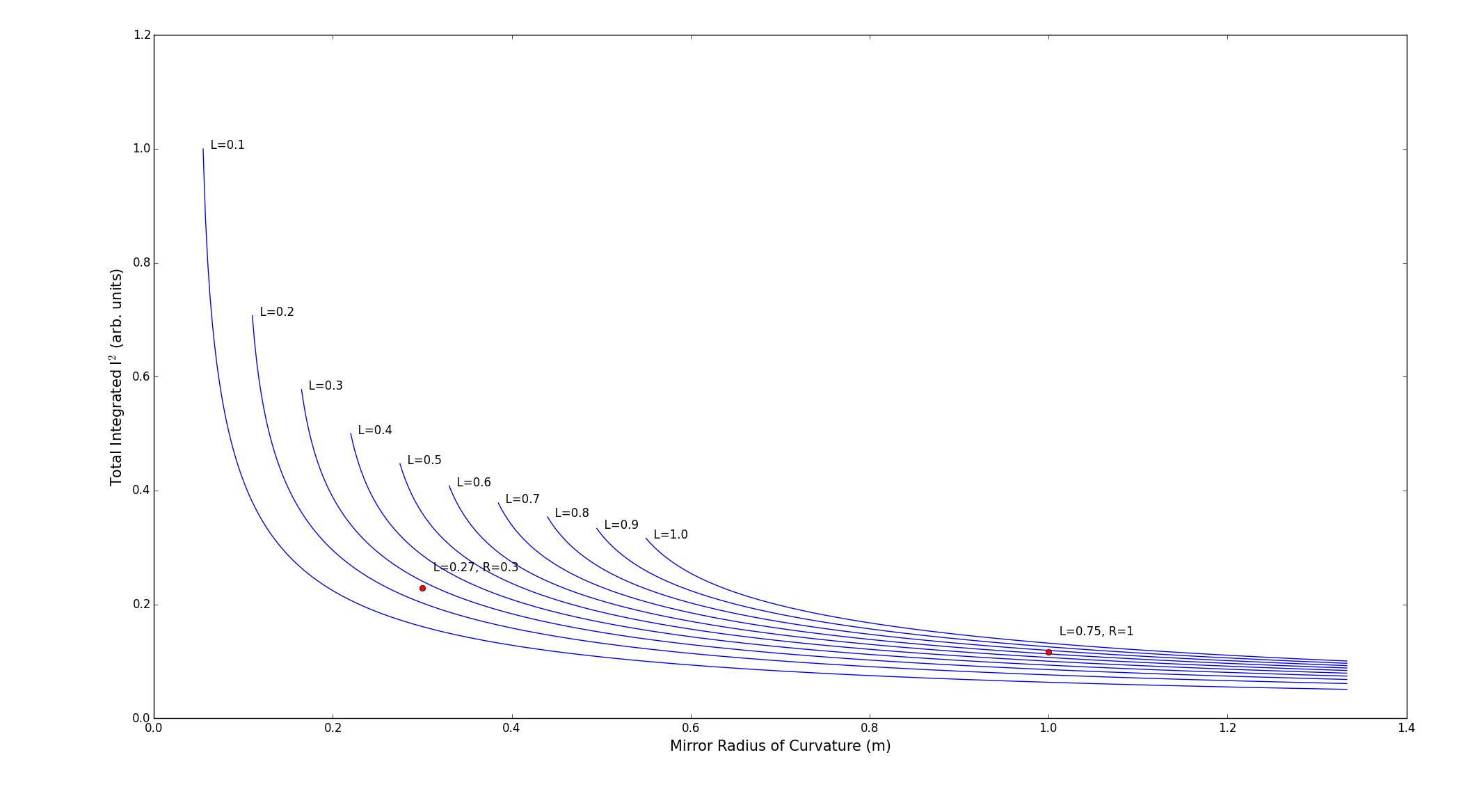
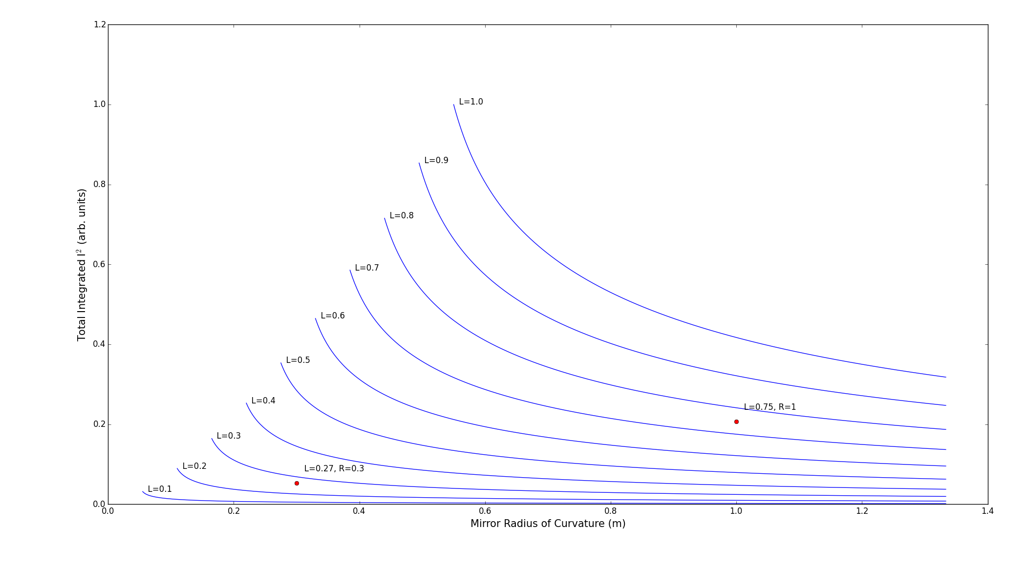
We're not quite sure if or how well this would work, so before designing a new cavity we're trying out an old one we had (L=.27 with mirror radius of curvature=.3)
So that's where I'm at now. I've got the new cavity in but have been having a bit of trouble with the mode matching. It seems doable though and I'm not going to worry about the mode-matching being perfect (it probably wasn't with the old cavity). I just want to see if there's a big difference in lock-performance or not.
5/28/15 Changing out the old Raman cavity! More to come, just recording it's position here. From the corner of the table near the computer, the corner of the cavity (nearest the computer) is 45 by 6 holes away. (i.e. the corner is 0x0)
Also need to move the walking mirrors for mode-matching purposes. The Dichroic was at 36x7 and the other is at 36x3.5. The pickoff is at 41x7, and the prism is at 41x10
5/18/15
Nick wants to borrow a vescent setup and so I'm gonna do him a solid and loan it out for a bit. Here's the settings for the 1064 pre-lock, which hopefully someday will be useful:
gain: 2.75 first integrator: 1kHz second integrator: off differentiator: 20 kHz diff gain: 23 turns aux gain: '--', 'low'
Saw green from the HeNe!!!
I'm getting about 0.71 mW incident (chopped) on the cavity and about 0.56 mW inside. I couldn't detect a signal from the green, but it was very faintly visible after the diffraction grating. This is good, but the orange laser is not a whole lot more powerful. If I can't detect the modulated narrow frequency light from the HeNe, the orange laser isn't looking too good. I'm getting ~12mW chopped power incident on the cavity from the orange laser (with the thermal head centered at 1024) and about 2mW inside :-/
4/28/15
Eventful last couple weeks. I finally ordered the new computers and Nick and I spent a productive day building them. We also won a SWAP auction for 30 monitors for only $375. Every computer in the lab will have 2 monitors minimum now. I spent a while writing a python program to calculate what lenses to put where to mode match a beam to the cavity (or to any shape). The orange laser was just so big by the time it got to the table it was hard to just eyeball it with lenses. I'll probably still make a few edits but I'll put the program up eventually---it worked great and the beam is pretty well focused through the cavity now.
I ordered a fast 2 GHz photodetector from Thorlabs--the DET025AL. Since the rep. rate of the orange laser is 100 MHz, I was hoping we'd see pretty high peak intensity on this, but so far I can't see any AC signal. I think maybe this one is just defective. In the meantime, I'm going to not try to detect individual spectral components and just the whole modulated beam. So no monochromator, just short pass filters to let through light under 800 nm. Using the same settings as when I did this for 780, I get fluctuations of around 75 mV out of the lock-in. Roughly 1 nW=1.77 V, so with only 10 mW incident on the cavity, it might be a little rough seeing a signal.
4/17/15 The beam quality is somewhat lacking with the orange laser, which makes it hard to match to the cavity mode--it's currently very poorly matched which is at least part of why I can't detect anything. It doesn't really behave as you'd expect when it's collimated. I checked how well it would focus--with a 40mm lens, I got to to about 30x60 micron diameter. The beam was about 5 mm before, so the diffraction limited spot should be closer to 10 microns. Still, we only need to focus to about 800 in the cavity, so no big deal hopefully. I'm vaguely trying to write a python thing so that I can say what initial beam I have and what I want to be and it tells me the best lenses to put where.
4/15/15 Been working on modulating the PCF output of the orange laser. Got the 1064 beam up and running again and locking as well as it used to. 780 was very easy to get modulated again, though it's always a little hard to actually detect with the lock-in. The 780 diode burned out--started outputting only a few mWs even at high current, but I replaced it and it's working fine again. I now have the 780, orange laser, and the HeNe aligned to the cavity using 2 flip mirrors. Each beam has two separate mirrors, but they're not all independent. Still, it was the cleanest setup I could come up with and after the initial difficult alignment it's not much of a problem. I'm trying to use a monochromator instead of the diffraction grating setup like before. I'm still chopping the beam and looking at it on the lock-in It works well enough for the 780 at least. My hope is that it will give me some sort of spectrum-resolving ability. I couldn't detect anything from the orange laser yet though--I think there's just too much unmodulated light getting through so that when I change its alignment to the cavity I'm mostly affecting how much light makes it through the monochromator. I got some low-pass filters though that should cut out everything but the modulated light though which will hopefully help. I haven't tried to make the beam-profile better match the 1064 yet either which will help increase conversion efficiency.
I've also been trying to modulate a HeNe mostly just to see if I can. It should shift to 532nm and be pretty visible, but I couldn't see anything yet. The beam profile probably isn't good though or the polarization and it's so low power, so I'm not surprised. They have some 20 mW HeNes in the optics lab maybe I should borrow. I don't want to waste too much time on this though since it doesn't really show anything different from what we've done before--it was mostly just something to do while waiting for the filters for the orange laser.
I was hoping the orange laser would be easier to detect since it's pulsed, but it seems like the pulse width is too narrow--I tried looking at it on a photodetector and it didn't seem any easier to detect than a CW beam.
3/16/15 Major findings of the last month:
We got the interferometer set up again and, surprise, there's no linewidth narrowing from the ebay mirrors. So I switched back to the layertec mirrors (the two curved ones--again it's unclear why it doesn't work well with one curved and one flat). The linewidth looks around 20 KHz, which is at the limit of what the interferometer can measure, so the narrowing is potential less. Some sources suggest you need a substantially longer fiber delay than the coherence time of your last (like 6 times as long) but I've seen it quoted that being equal is fine too. It's clearly narrowing substantially though.
The layertec mirrors never locked very well. I attributed this to bad slow feedback for a while (all the piezo would ever do is rail). It seems like the actual problem though was etaloning between the fiber launch and some other element. Essentially the pre-locking cavity peaks were inside a larger envelope of some much lower finesse cavity. This explains the strangely high sensitivity the walking mirrors seemed to show. I put an isolator in which mostly fixed the problem. It seemed to substantially reduce the error signal and transmitted signal though--way more than the 20% or so lost through the isolator. I'm unsure why since it the shape of the beam shouldn't be affected. But the cavity locks okayish for now--upwards of 10 minutes when working well. Improvement can certainly be made, but for now I'm working on the Raman cavity since the basic features I want from the pre-locking cavity are there (much longer lock times than the Raman cavity and substantial linewidth narrowing).
Little luck with locking the Raman cavity. I've been working on making a slow-feedback locking circuit (see Zach's description under equipment list) but am still having a few issues. I borrowed on of his completed circuits though and haven't had luck, but still have a few things to try. I had thought our old slow box was broken since the power supply always went a little crazy when I plugged it in, but I realized today that the manometer is actually drawing way more current than it should. Plugging the slow box in just always pushed the power supply over the edge. The -15 V line was actually running closer to -11 V. I'm not sure how long this has been going on. I've just unplugged the manometer for now since I don't really need it when I'm just operating under vacuum.
The low pass filter after the mixer on the PDH setups seems to be greatly lowering the error signal. Like most things, I'm not sure why. I'm taking them out for now on the grounds the added signal is pretty much too high frequency to do anything in the servos, and any detrimental effect it has is probably greatly outweighed by the decrease in SNR.
I'm getting worried this isn't going to work. I guess that was a risk when I started this, but I really thought if we got the laser linewidth on the order of the cavity linewidth we could lock with just slow feedback. I don't really see how that's different from what Nick does with the SHG cavity. At least I've learned a ton, and I've really only been trying something that might potential work for a day or two. I can always table this whole things for a bit and come back to it in a few months. I think I might be starting to become frustrated with it to the point where I'm not working effectively. Probably in another week or so I'll start trying to set things up to modulate the pulsed orange laser, which is something I think I can do.
2/11/15 Got very poor locking by using the old 1555 slow feedback box on the Raman cavity while the laser was locked to the low finesse cavity. I was having trouble sending two error signals to the Vescent box since they seemed to interfere with each other, so I'm trying this method for now. Having the laser locked to the low finesse cavity seemed to help stability with the Raman cavity, but not for transmitted power. I think we're not getting any or enough linewidth narrowing, so I'm going to swap the cavity mirrors again. I think the problem with the Layertec mirrors wasn't that they were too high fiensse, but that we weren't impedance matched (I still don't think we understand that very much though). So I'm going to use the two curved mirrors which should be pretty identical and presumably more reflective than the ebay mirrors.
Good locking settings for the ebay mirrors are: 1st integrator: 100 Hz 2nd integrator: 1 KHz-1MHz or off differentiator: off aux gain: who cares, can lock without it prop gain: 4.0 turns--sometimes turn up to get it to lock then turn back down a bit to stabilize.
2/5/15
The eBay mirrors ended up working. I'm using two curved ones with R=75 cm, so the waist is in the middle of the cavity now. The size was only about 10 microns different, so I basically just moved the cavity forward 5 cm, and what do you know--huge transmitted and reflected peaks. I'm guessing it's better because the mirrors must be very close in reflectivity, but it's weird because the impedance matching equations (see the python script) suggest that it shouldn't be a huge deal assuming the reflectivities differ by a couple tenths of a percent (seems likely for any cavity mirrors). Maybe there was something about the plano-concave configuration? We don't quite understand something here, but sometimes you just gotta move on.
With a bigger reflected signal it wasn't too hard to get the laser locking to the cavity. It was easier to lock to non 0,0 peaks. Even though the signal was smaller than the 0,0 mode ones, they were more stable in transmitted power, which made it easier to lock to and the lock more robust. I don't want to send to much power to this cavity though since we need most for the fiber amplifier, so for now I'm locking to the 0,0 mode but I might switch back. The cavity seems much more responsive than before. When I adjust the MML, I can see the cleanness of a FSR change. It looks about as good as the Raman cavity.
The lock still isn't perfect, but it's much better than the Raman lock--I've gotten a lock maintained for ~1 hour, which is already good enough. I think I can probably still improve it. In addition to the locking circuits, putting the cavity in a padded tube might help damp low frequency noise which seems to be the dominant error signal frequencies.
So now is the hard part of the whole locking 1 laser to 2 cavities thing. There's a lot of ways I can see to do this. We generate a second error signal from the Raman cavity--we can try sending this to a lockbox and feeding back just to the cavity piezo (maybe the laser line is sufficiently narrowed from the low-finesse cavity). We could send both error signals to one lockbox (it turns out you can add two signals just be using a splitter backwards! Who knew? No one in lab, that's for sure). But that could be tricky to try to get it to lock to two things at once, even though the frequencies are pretty different. After locking one, trying to adjust the DC offset to get the other signal locked would probably disrupt the first lock. I could probably lock the low-finesse cavity with just the fast feedback and then try using the aux servo output on the same vescent box to lock the Raman cavity--this has the same issue though of having to adjust the DC offset, but would have less competition with the fast feedback.
What I think is most likely to work is to use a second lockbox and feedback either directly to the laser diode or combine error signals and send both to the current driver (I don't see any advantage of feeding to the diode, and that would be difficult/invasive to setup). I tried the combining error signals and feeding back to the current driver (slow-feedback to the separate piezos today). One problem I had was with the RF signals. At first I used a second RF generator for the Raman error signal, but I noticed a lot of noise. I eventually realized it was at 5 Hz and tracked it down to the fact that the RF generators aren't super accurate and the signals differ by about 5 Hz even when they are both set to exactly 50 MHz. The problem got a lot better when I reduced the frequency of 1 by 5 Hz, but it was still a little off and I didn't have the resolution to improve it more. So it seems like all the signals need to come from one RF generator. But without some crazy combination of splitters, I can't send the same power to all components. I eventually upped the power of the 1064 RF generator to 13 dBm (this is now the normal power that should be run at), split the output to send 10 to the Raman error signal, which leaves 10 to be split into two 7 dBm signals for the EOM and low finesse locking signal as usual. But this means that the Raman cavity error signal is getting 10 dBm instead of the usual 7. It probably doesn't really matter, but this is different than before. Maybe I can find an attenuator that'll work?
Anyway, once that was all worked out I wanted to try the double locking thing. In short, it didn't work yet but it seems like it could be possible--I had two error signals going into the current driver and nothing crazy happened and both Vescent boxes seemed like they were almost locking. I was having trouble with the low-finesse lock, which I think it just because the RF power is probably slightly different, and more importantly the summing signal thing (backwards splitter) probably introduces a phase delay that I haven't properly accounted for. I want to check with RF or function generators tomorrow and see if I can figure out how much it delays things. Hopefully there's no dispersion because I don't know how I could fix that.
It would also be good to check the linewidth when locking to the low-finesse cavity once new Zach gets the interferometer running.
1/22/15
Still haven't heard back from Layertec. Thorlabs says they can do it, but it'll be ~7 weeks, so I'm holding off on that for now. Deniz says Lambda Research is usually pretty fast. I requested a quote from them but haven't heard back yet. Zach found some mirrors on eBay that don't give a ton of info, but seem like they might work. I ordered them and hopefully with that we can make something happen.
1/20/15
I put an arrow on the backpolished E03 mirror pointing towards the side that was facing upwards in the packaging. I think this is the "back" side that is less well polished. The mirror didn't seem to help the signal strength though, and in fact made it worse. I flipped the mirror around too in case I got it in backwards, but I didn't notice any change. The problem now is probably that it is poorly impedance matched because the reflectivities are so different, which apparently is a thing. I updated that python program to account for this--we're probably only getting a few percent of the full height of the reflected signal for resonance dips just because of the impedance, so that's probably the issue now. I'm seeing if Thorlab can make us a custom curved mirror (2 E03s would give a finesse of ~800) and I'm talking to Layertec about making a pair in the 2000-3000 range. We want the highest finesse we can get away with that will still be easy to lock and stay locked, but we're not sure what value that will end up being.
1/15/15
Zach and I both kept having trouble getting much transmitted signal and any reflected signals. We thought maybe we weren't mode matched well, but we'd both tried a few times and that didn't seem to be it. It was also possible that the laser linewidth was much bigger than the cavity linewidth. I made a python thing here that calculates the power of an incident beam that is coupled into a cavity based on the spatial and frequency profiles. The cavity mirrors listed a selectivity of about 99.98%, which would give a finesse of around 16,000. The cavity linewidth is just the FSR/finesse, so it would be ~95 KHz, so with our ~500 KHz linewidth laser, and even very rough spatial coupling, we should still have been getting some power. We thought maybe the radius of curvature of one of the mirrors was wrong, but we took out the cavity mirror and found that it focused a collimated beam at ~25 cm, which would give the correct R of 50cm. In retrospect this probably wouldn't have mattered as much as we thought--the spatial coupling curve is quite forgiving.
Eventually we thought maybe the finesse was higher than we thought, and I measured the reflectivity of the plane mirror and found it to be about 99.998%. It's safe to say we'll never be buying German made optics again! Assuming a similar reflectivity for the curved mirror, this would give a finesse of 160,000. The linewidth would be very narrow then, and we'd only get about 2% power even ignoring spatial coupling. This is likely the issue. We ordered a back polished E03 mirror from Thorlabs which we'll swap in. That has a reflectivity closer to 99.6%, which would bring our finesse down to a more manageable 1600.
1/12/15
I briefly was getting the laser to lock for a couple second a few times over the last couple days, but couldn't improve it much. I think I'm seeing pretty good cavity peaks now though--stable and what appear to be a couple free spectral ranges. I want to figure out what kind of piezo is on the laser though, so I can know how much voltage change should give a free spectral range (so I know I'm not way zoomed in on some higher mode stuff).
I can't see anything for a transmitted signal with the PDA10A, without using an amplifier which would reduce the bandwidth too much. I don't see dips on the reflected signal, so this might be part of the locking problem. Maybe I'm not mode matched well enough and aren't getting enough power. I thought it a different lens/cavity position configuration I was seeing peaks on the PDA10A, but that seemed like it had worse mode-matching. Well it was pretty spot on in one dimension, but not even close in the other. Right now it should be pretty close in both, but maybe the last little bit matters a lot and so it was still better overall before. I'm going to re-profile the beam tomorrow and see how close I am and maybe see if I can improve it.
1/8/15 Nick had the really good idea that my peaks might be so unstable because I wasn't ramping at a high enough frequency (James from Saffman said this can be a problem), and I don't think I was at a high enough amplitude either. I switched to the external ramp and it looks much better now. I think I'm seeing a few free spectral ranges with not much non-0,0 modes, but the reflected signal is very weak (I can't really see it). I'm going to try locking though and see if I can get anything. I'm just using the vescent box for the 1064 cavity beam, so here are the current locking parameters for when I need that to work again:
First integrator: 10 KHz
Second integrator: off
Differential: 500 KHz
Differential gain: 22 turns
Auxiliary servo gain: 4.5 turns
Proportional gain: 3.3 clicks
Phase delay line: ~9'2"
Winter Break Update
Pre-stabilizing cavity Wow, I've really let this get out of date. We've moved forward with the pre-stabilizing cavity idea. We needed to buy a lot of optics, but realized we could get away without another EOM by just picking off after the EOM on the main experiment. Even when we feedback to the same current driver, the error signals shouldn't interfere with each other, because their frequency components ultimately depend not just on the EOM modulation frequency, but on the cavity length too.
Zach made some cavities with a finesse of a few thousand. They're made of a special steel that has a very low expansion coefficient, and so they should be pretty stable. I didn't realize mode-matching was so important for cavities, but it is and so I had to learn a lot about that and Gaussian beam optics. Nick has a helpful MATLAB problem for calculating the coupling parameters to the cavity, which I've uploaded here. I also found this youtube video pretty helpful and the few chapters about lasers in the Pedrotti optics book.
The cavity is 10 cm with one plane mirror and one with a 50 cm radius of curvature, for a [math]\displaystyle{ g_1=1 }[/math] and [math]\displaystyle{ g_2=0.8 }[/math]. I used the spinning camera for measuring the Gaussian beam parameters to figure out what kind of lens was needed to mode match. With the initial beam, I could only match the x or y component unless I got some cylindrical lenses or a prism pair, which seemed like too much work, so I decided to couple to a fiber to get a mostly circular output. I found the correct mode matching lens to then by an f=750mm about 10 cm from the fiber output and then another 55 cm to the cavity. The lens is on a 1-d stage for small translation adjustments.
I was having difficulty finding a signal from the cavity for a while, but looking at the reflected signal rather than the transmitted proved useful. The reflected signal is made with a quarter wave plate and a beam cube to provide some isolation from the back reflections and to allow the power to be adjustable. The center of the cavity is at a height of ~3.375 inches, so I marked that on the fluorescent stone and walked the beam to that height before putting the cavity in. Then by overlapping the horizontal back reflection with the incident beam, I could usually see peaks on either the reflected or transmitted photodiode. The reflected signal looks very weird though--very jagged without any obvious periodic dips, but it seems like it has to be result from the cavity transmission since it only is visible with the ramp on. The transmitted signal looks more normal, except it is extremely unstable--just barely touching a mirror without even adjusting it will make the peaks jump around, and they fade in and out just over a few seconds by themselves. I've gotten it aligned where it looks pretty good except for how unstable it is. Maybe I'm actually locking to a of axis-eignemode or whatever and these are just the biggest peaks I've seen so far and I'm mistaking them for a 0,0 mode free spectral range. Maybe the cavity mirrors are slightly misaligned.
We thought the instability might be caused by the non-angle polished fiber I was using, so I switched that out but it didn't seem to do anything. It doesn't seem to be back reflections feeding back to the laser either, since looking at the laser on the spectrum analyzer shows nothing weird even when the cavity peaks are drifting in and out. The power reaching the cavity is pretty constant too, so I don't think it's the fiber being weird.
That mostly brings us up to today
We got a new IR scope from the surplus store. We were having trouble with it for a while, but we traced it back to just a bad connection with the battery case and swapped it for the case from the old IR scope. It works great now.
We were thinking of trying to modulate the output from the pulsed laser before we broaden it with the PCF as a preliminary experiment while we're still figuring out all the PCF stuff. The wavelength would be too close to the pump beam though, so the optics wouldn't work for us to be able to pass it through the cavity. We thought we could maybe frequency double it first and then send it in, but Deniz thinks we'd need about 10 mW of green to do it, and I'm not getting more than a few hundred μW from the doubling crystal. I tried changing the temperature of the crystal some since that's supposed to affect the wavelength it responds to, but that didn't seem to do much. I might try expanding and more tightly focusing the beam to increase the intensity if I get stuck on the cavity stuff.
12/3/14
Been swamped with classwork lately, but a few lab things worth noting.
I've pretty much concluded the 2 photon experiment can't be done with the current setup. The way Josh did it previously was by broadening the cavity peaks and then tuning the frequency differences with the laser piezos. He could then scroll to a different broadened peak, which would be about 200 MHz away. We're at higher pressure and locking makes the frequency jump a lot and in a pretty unpredictable way.
I think we need to pre-stabilize the lasers with a low finesse cavity. This will 1). make locking to the high finesse cavity much easier. The lasers would potentially stay locked for a lot longer so that we could just focus on tuning them rather than keeping them locked. And 2). Give us another way to tune the laser frequency--we could lock to different peaks of the low finesse cavity to change frequencies by its free-spectral range.
Another way we could maybe do the experiment would be if we could recreate the peak broadening behavior. We used to turn off the slow feedback box and ramp the cavity or laser piezo. When the piezo hit the resonance position, the fast feedback would keep it resonant for a bit (even as the piezo kept moving), resulting in a broadened cavity peak. This doesn't work with the vescent box even when we unplug the piezo, which I think is because the minimum frequency the the current driver responds to is different from our previous setup. I'm waiting to hear back from vescent about this issue. In the mean time I tried making a high-pass filter so that I could manually adjust it (well, I couldn't decrease the minimum frequency, but I could effectively increase it though). I wanted it to be able to filter out frequencies below a couple hundred Hz, but it didn't really do anything though, which might be partly because I used a pot with wire coils which probably has a big impedance, but from talking to people it also sounds like you need to use an active filter at low frequencies. I probably should just buy something then, but I'll wait until I'm more convinced that will help.
The manometer also seems like it got calibrated somehow, since it was saying the cavity was pumping down to about 20 times lower pressures than it usually does and that seems unlikely. I unplugged it and reconnected it, and it gave more normal values, but it's a little bit offset from where it used to be, probably by 10-20 mV. That shouldn't really matter since most of the pressures we're at are in tenths of volts and I can't really get those accurate to 10 mV anyway.
There was also an issue with the 1064 laser giving unstable wavelength readings. Like fluctuations of about 500 MHz every second (I mean, it stayed withing about 1 GHz over pretty long times, but just bounced around within that). This turned out to be because of the multimode fiber we were using. The frequency wasn't actually doing this, but the fiber was supporting extra spacial modes which was confusing the wave meter. Using a single mode fiber gives readings stable to 10s of MHz, which makes more sense. I couldn't get enough of both 1064 and 155 coupled with a single mode fiber, so I might need to order one that will work better, or just keep in mind the deal with the 1064 one.
Vescent also put an updated manual for the servo controller up, and it has some helpful info. There are apparently some secret switches you can only get to by taking the side panel off, a few of which do interesting things. One secret switch lets you set the box to ramp in "master" mode rather than "slave". Previously we had to input an external ramp, which we could then turn on or off and adjust the amplitude of. There's nothing really wrong with this that I can see, but it's just another piece of equipment and nest of wires to complicate things. I switched to the internal ramp, but I might need to change back if we ever get the peak broadening working again, since you can't ramp while locking with just the vescent box. There's also a switch to change it so that the vescent box will only output a positive ramp. This is good since we don't want to put a negative voltage to the piezo. We normally have to manually put an offset on it each time and then take it off at the end of the day (since we don't want to leave a voltage on the piezo). This also means there's not really a reason to output to the Thorlabs piezo controller. All it basically does is serve as a buffer to prevent negative voltage going to the piezo, amplifies the signal, and lets you make small adjustments. The internal ramp seems strong enough, so I've switched to just using that for now. I'm not sure if it's better that way, but I'm hoping maybe it will make the lock better since it kind of has more direct control over the piezo now without having to go through another device with its own gain and phase delay.
11/19/14
Once again, 1555 locked at 0.05 atm with minimal adjustment. This is a very good sign. I've got a new procedure for getting 633 back if the 780 gets misaligned. No cameras or IR viewers required and it's quicker and easier--put a fair amount of gas in (maybe 1 V or so) so that there aren't many spacial modes without 633 and there's a lot of it if alignment is good. On the 1064 side of the cavity, turn down the power and use a card to overlap the 1064 and 780. Then turn the power back up, lock the 1064, and on the 780 side of the cavity use the other alignment mirror to overlap the transmitted 1064 with the 780. Repeating this 2-3 times will get 633 back depending on how badly aligned it was. Optimal alignment will change slightly when you switch back to whatever pressure you were working at, but it should still easily be detectable and so is not hard to fix.
I'm getting closer to being able to do the 2 photon experiment. Both lasers have been locking pretty well at this pressure, 633 is easily visible with just the 1064. Now I just need to practice tuning the laser frequencies and figure out how to keep them that way even when they lock and jump frequencies.
I think pre-stabilizing them with reference cavities would help a lot, but I'll keep trying this for a bit and see if I can make it happen without them. There's still probably a few weeks before the Moglabs wavemeter is ready, and the pulsed laser is still not set up either, so it's not really holding much up.
11/18/14 Hot damn! 0.05 atm might be the magic pressure. 1555 locked again today with only small adjustments. Good settings seem to be integrator at 5 kHz, differentiator at 500 kHz (this definitely seems the best setting for all pressures). Differentiator gain seems to give a trade off between power and stability. Prop. gain around 3.75. Optical feedback at 1.4 V (I didn't realize the scale on the oscilloscope had changed--I've normally been doing around 400 mV, but this actually worked well with different gain settings. Maybe more optical feedback, less gain is better if I can get it to work).
11/17/14
I've been mostly still trying different locking settings. The 1555 is amazingly inconsistent and I'm not sure what's really changing day to day. Both locks work better under lower pressure though, so I've been trying to find a good compromise between getting 633 generation and easy locking. 0.38 V (0.05 atm) seems like a good spot. There's 633 at a fair number of cavity modes, and it's easily visible in mirror or on the photodiode. I'm going to stick just at this pressure for a while and maybe I'll be able to learn more about locking just at this pressure.
It also occurred to me that we might be able to run the lasers are higher power. The limiting factor is the isolators, but the 1064 one is rated for 60 W and 500 W/cm^2. We're obviously under 60 W, and I think our intensity is ok too. At 30 W of input, we would need a beam larger than 1.4 mm. I'll measure it when I get a chance. The isolator's aperature is 4.7 mm, so we could always expand the beam and re-collimate it after. That would be a lot of trouble, but we could increase our single beam conversion efficiency by 50%.
11/5/14 I'm not sure what happened, but something must have gotten bumped and the 1555 was completely misaligned--no cavity peaks or anything. It was good practice at setting that back up at least. The best way seemed to be to turn the power way down and look at the incident beam and reflected beam with the card and try to overlap them in two places. Then I moved the transmitted photodiode and took off all the filters/covers and put it right at the transmitted side of the cavity. Using the HeNe was helpful for making sure the photodiode was pretty much aligned to where the 1555 beam would come out. Turning the power all the way back up and making small adjustments with the walking mirrors usually got some very small peaks which could them be optimized.
Locking is still inconsistent. It's not too bad under vacuum, but with gas settings that work one day don't work as well another, and the higher the gas pressure the worse it seems to be. I lowered the pressure only about 0.57 V (about 0.07 atm), and was able to achieve pretty good locking--~150 mW transmitted, with the best locks stable for a few minutes. I was able to simultaneously lock with 1064 too (the bandpass filter helped), and I think I can still get sideband generation at this pressure, although the 780 was misaligned and I'm not able to see any 633. Hopefully after fixing that, I'll be able to get some 633 generation and have consistent locking settings and performance at this pressure.
Current successful settings for 1555 lock at 0.07 atm:
course gian: 4 clicks
fine gain: bit over halfway
first integrator: 10 kHz
differentiator: 500 kHz
optical feedback: ~300 mV
11/3/14 The 1555 lock works pretty well under vacuum when it works. Getting it to work is a problem. It seems to need different settings everyday, so apparently is very sensitive to small fluctuations. When it is working well, I've gotten between 800-1000 mW that is pretty stable in power (often less than 20 mW fluctuations), that can last for over a minute. Again the necessary settings seem to differ everyday, but usually a good lock can be achieved just by adjusting the optical feedback, proportional gain, and auxiliary servo gain. The first integrator is set at 5 kHz, the differentiator is set at at 500 kHz (gain set somewhere in the middle), and the second integrator is off.
Try optical feedback somewhere in the 100-600 mV range, and the proportional course gain at 4 clicks (the necessary settings for these two seems to be loosely inversely proportional. Sometimes the piezo voltage will max out (158.6 V), which usually means the gain is too high. Sometimes lowering the proportional gain helps, but this can also cause the laser current feedback gain to be too low, so try adjusting the auxiliary servo gain independently. Sometimes it will still lock fine at very high power with the piezo maxed out, which is confusing. Maybe it is still actually making small adjustments, which just aren't visible, or is the piezo actually doing very little?
Also it basically refuses to lock by adjusting the cavity piezo and you have to use the DC offset on the lock-box instead. Who knows?
The necessary locking settings are very different even at just 0.1 atm. I have the first integrator all the way down at 2 kHz. The proportional gain and optical feedback I've had to adjust all over the place. I had it locking well briefly and was getting about 150 mW, but lost it pretty quickly when trying to optimize it. The window of "good" settings seems much smaller with gas. The laser piezo is especially difficult--with the auxiliary servo gain too high (or just the overall gain too high), it maxes out the piezo, but when just a bit lower it doesn't seem to do anything. In fact I would get locking signals that were reminiscent of ramping with just the fast feedback on back in the old days (suggesting that the slow feedback wasn't doing much).
I did finally figure out where I would get weird signals from the transmitted 1555 photodiode (sometimes negative, sometimes positive when locking; the signal would quickly jump up and then fall down to center around zero even with the output power fairly constant). They seemed like symptoms of AC coupling even though everything as set to DC, but it turned out the photodiode is premade to AC couple. That's slightly annoying because it makes it hard to tell how good a lock I have without measuring it, but a new photodiode it expensive (we don't have any extras at this wavelength), so I'll make do for now.
10/29/14
I don't think the cavity leak is a problem for now--don't usually run it at less than 0.1 atm, or 760 mV, so the leak is a pretty small fraction of that. I got both locks working individually, but when trying to lock together the 1064 beam seemed to interfere with the 1555 lock. I think it's the generated 807, since there would only be interference in cavity modes where 633 was being generated (and so 807 was also). This is probably fixable with just a notch or bandpass filter. I also noticed that the error signal on the 1555 was very noisy again, at least compared to the 1064. Not the 1 kHz noise I was getting for a while, but just generally very staticy. I'm not sure if this is new or I just didn't notice it before. I eventually tracked it down to the low-pass filter, which doesn't seem to be doing anything. Switching it with the 1064 one fixed it. It's not locking well now, but presumably I'll have to retune some parameters now that there is a working low-pass filter and that there is gas in the cavity.
10/24/14
I think the cavity has a small leak. At room temperature, it will pump down to ~12 mV, but will be up at ~30 mV by the next day. This is probably too small to be a big deal, but I should check with Deniz.
10/22/14
I'm not sure what was going on with the laser driver, maybe a loose cable? I haven't had that problem again in the last week. I got the 1555 lock working better and got to about 600-700 mW of power. However, when it was locking well and the noise was low, the transmitted signal looked like a sine wave with a frequency of 1 kHz. Clearly the noise I was having was causing a problem. It turned out that the RF generator was putting side bands on the signal at 1 kHz. I swapped RF generators which seemed like it should help a lot. I got up to ~850 mW, but I think there is more optimization to be done since the phase delay was changed. The lock is pretty inconsistent from day to day, but I decided to put it aside and get the 1064 working again and then add gas before trying to optimize the locks much more.
The 1064 was much easier to get locking, although the transmitted power is low. Only around 70 mW after playing with most of the parameters fairly extensively. I'm not sure why it is lower, but the lock is pretty stable.
I'm still confused as to why I don't see the changes in error signal that I would expect when I change the phase delay. There doesn't seem to be much difference on both the 1064 and 1555. This is definitely something to focus on because it seems like it could be having a big effect on the lock.
10/15/14
I tried to follow the various signals through all parts of the PDH circuit. I made slight adjustments here and there, and most notably added some BNC length to change the phase delay on the local oscillator. I also turned off the integrator on the lock-box and so was just using the proportional gain. The error signal should be linear near resonance, so do we even need differential and integral adjustments? I saw the best performance yet, with powers over 300 mW and fairly consistent.
I also saw a lot of weird behavior today. Ramping was very inconsistent, and it was hard to see if the laser was aligned even when I knew it was close and I should see some peaks. The oscilloscope near the cavity would show very little or no signal and sometimes the other one would show much more. It seemed more than just scaling, but a difference in signal to noise ratio. They are getting the same signal that is just split and the oscilloscope settings were comparable. I also didn't see the changed in error signal I would have expected when adjusting the phase delay length by half a wavelength (~1.9 m) (see the figure on page 32 of Green's thesis--everything looked like the pi/2 and 3*pi/2 plots, no matter how much cable I changed). I'm also still seeing noise on the error signal and DC offset channels. It seems different everyday. It's only present when the RF is on, but today there was a lot in the 20 Hz region (yes, Hz) on the DC offset channel. I still don't know what the cause might be and if it's a problem.
The weirdest thing by far was the current driver starting oscillating somewhat again, by maybe 1-2 mA. It's don't think it's bad temperature tuning again, because the temperature was staying within tenths of mK to the setpoint and I adjusted the setpoint too in case there were any weird resonances. I wanted to repeat the threshold test, and I couldn't turn the current down below 100 mA. At the lowest setting, that was what it output. Turning it off and on and unplugging the servo connection eventually got it lower, but then it would just start creeping back up without me adjusting anything. I checked with a power meter and the laser powers were consistent with the current value that was displayed.
10/9/14
I tried to track down where the noise was coming from. The DC error output on the vescent box only is noisy when it's connected to the error signal and the RF is on (doesn't matter whether the laser is on and there is actually an error signal). The full height is about 15 mV of noise. I checked the laser diode output using a photodiode and the noise doesn't seem to be coming from there. Most likely seems the RF amplifier in the circuit, although the low pass filter isn't cutting this as much as I'd think either. I tested the amplifier by itself though and it didn't show any sidebands, which would have been the obvious cause. It does have signals at integer multiples of the input RF signal, but those are all around 10 db lower. I checked the same amplifier on the 1064 setup and it showed similar behavior. The vescent box on the 1064 also shows similar noise with, although slightly less, so maybe nothing is broken and this has always been there.
10/7/14
Ordered 2 HeNes from Ebay so we can return the ones we've been borrowing from the optics lab. I've been wondering if maybe the amount of optical feedback isn't right for the 1555 locking circuit. I was able to get kind of a lock with only the first integrator on (20 kHz). Then I adjusted the optical feedback and then the proportional gain. The best performance seemed to be between 2-3 V optical feedback when the circuit isn't locked. It's currently set at 2.5V, which will give some locking with the proportional gain course knob 2 clicks up and the fine gain most of the way up.
I tried switching to the current 1064 slow lock (the old 1555 lock--i.e. the one that says 1555) (the 1064 is broken :( )) still with the vescent for the fast lock. Performance was still bad--I'd got a consistent "lock" with only power of a few mW transmitting from the cavity. The lock is still very "fuzzy"--not really a jump up in signal but rather the whole signal looks very noisy. I noticed that the DC error output on the vescent box is noisy, with a signal at very close to 1 kHz. The error signal seems noisy too.
10/1/14
Diode performance seems good on the OSA too. The peak from the threshold test was single mode and stayed single mode when I increased the current up to the operating value. When trying to set up the locking circuit, it would only occasionally go multi-mode and would quickly return to single mode when I turned down the amount of feedback (previously this would generally require re-scanning with the grating). I never had to touch the grating after the initial threshold test. By the end of the day, I had it locking using just the proportional gain and the first integrator on the Vescent box. The lock would quickly start falling but jump up again before disappearing entirely. This sustained for ~1 min, which is better than I've ever seen. The transmitted power was ~100 mW, which I think is lower than we had previously, but I'll have to look through Josh's notes. I think this will get better when I work with the optical feedback and the other integrator and differentiator. It was so much easier trying to improve the lock since the laser would stay single mode. Much more power is getting to the fiber amplifier too so it never shut off due to low power.
9/25/14
Ran threshold tests with the diode today--performance seemed good! Better than I had previously seen and better than what Josh had described. There are still multiple peaks at low power (although over a much smaller range than previously) and with the power up to ~0.5 mW (without well adjusted feedback), there is a single very clear spike in power (from ~0.5 mW to 1.3 mW) when adjusting grating position.
I'm not sure whether the old diode was bad, or if it was just the process of completely re-aligning this new one with the grating that ultimately improved performance. If it was the re-alignment, I think park of the trick was changing the horizontal grating adjustment to close to the middle position--maybe we were at too extreme an angle before to get good feedback. If we need to adjust the wavelength later it might be better to do what we can with temperature before moving the grating too much.
9/24/14
I've continued to have 1555 diode problems. Threshold tests were showing many small peaks of similar power. These individual peaks were generally single mode, but as I increased the current it went multi-mode well before reaching operating power. Deniz thought this was indicative of a failing diode, although Josh says this is consistent with the normal behavior he's observed (but that maybe it has never been working correctly). I tried re-collimating the laser and also moving the diode in the housing and re-tuning the grating and collimation. Neither of these procedures helped.
I decided today to change the diode before spending more time with a possibly bad diode. I was using the soldering iron at only 500 degrees to avoid possibly damaging the diode from heat, but this made it very difficult to solder a good joint. Eventually I changed to 550 and the process was easy and didn't seem to heat up the diode too much. The new diode works, although I haven't looked at its behavior closely yet. It might be worth trying to change the polarization since this can affect how much feedback goes to the diode and maybe would improve performance.
9/16/14
After looking at the power meters, the visible one definitely does not read 1064 nm accurately. The short story is that its values should be multiplied by 0.62. Graphs are here and here, full data is here. This makes the theory agree better with the experimental data, although the experiment is still low.
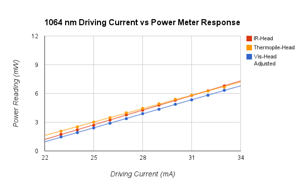
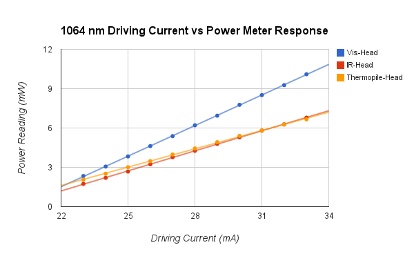
I've been continuing to work on the 1555 laser. The power has been dropping low enough that it sometimes turns the amplifier off, so I finally just re-aligned everything. See 1555 Laser Notes for more detail. I got the power somewhat higher, although it still seems low, so I wonder if the diode is having problems or if the feedback is very off.
9/11/14
Jared and Zach noted at group meeting today that they get pretty different readings using the visible power meter head for 1064 then when they use the IR one or the thermal one (which agree well with one another). Additionally it gives significantly different readings when set ~1064 vs ~1050, which suggests it's not well calibrated near the end of the it's range. I used the visible power meter head I used to measure the 1064 beam power for the recent 633 data, so I should check and see just how much the power measurements differ compared to the other power meters. Hopefully it's a constant offset or fixed percent and we can adjust the data accordingly. Deniz did a preliminary analysis and made a theory curve. It's about a factor of 2.5 higher than the experimental data. There are still a few effects to account for that might lower the theory, and accounting for the 1064 power measurement issue will undoubtedly affect things too.
Here is the tentative graph though.
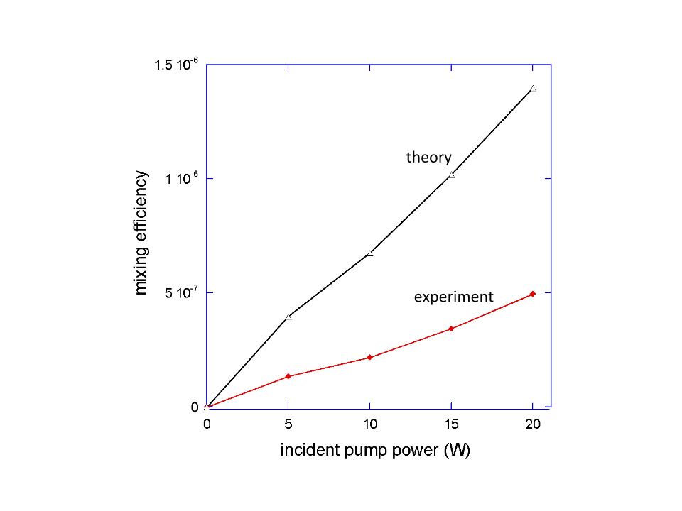
9/9/14 Still trying to get the 1555 to lock using the vescent box. It's very hard to keep the diode single mode--are these diodes just very sensitive, or is it not feeding back properly? Talk to Deniz. I'm reading a lot about locking--Josh's thesis is helpful, as is the original PDH paper. I noticed that on the the reflected 1555 signal is saturating the photodiode. I adjusted the ND filter closest to the photodiode from 1.0 to 1.5. This signal strength is adjustable with the waveplate/beam cube right before the photodiode, but it seemed like it was dumping a lot of power into the little fluorescent stone thing and I smelled burning (I might have imagined that though).
9/8/14
File:633 Conversion Efficiency Raw Data.xlsx
9/4/14 Previous table is just raw data and doesn't include adjustments for optical losses of stokes and pump. See data File:633 data.xlsx for adjusted version and with useful statistics. Josh has been gone starting this week. Very sad, although productivity is at an all time high. I've got classes again which means less time in lab though. I've spent the week mostly doing a bit of data analysis and trying to get the 1555 beam up and running again--I want to see how much that affects 633 generation if I can simultaneously lock 1555 and 1064. It took about a day to re-align the 1555. I could tell at some point I was getting a small signal on the photodiode, but it was so mis-aligned it was hard to optimize it at all. Eventually I moved the photodiode just past the transmitted 1555 side of the cavity and lined it up with the HeNe (which is a reasonable marker of where the 1555 should be if it's making it through the cavity. Moving the photodiode reduced a lot of the optical losses and I took off the ND filter. I was still getting a small signal that was hard to optimize, but looking at the ramping signal simultaneously proved useful. I knew a useful scale for 1555 peaks would fall within half a ramping period, so by adjusting the scale and then 1555 alignment I could eventually see peaks and optimize as usual. Not only was it very mis-aligned the but the oscilloscope settings were really off so I wouldn't have been able to see much anyway. I'll try to remember that for next time.
1555 is aligned now, although not locking. I'm trying the vescent box right now and hoping I can get that working, although I might have to switch back to the homemade boxes as before.
8/28/14
| Pump Power (W) | Transmitted Pump Power (mW) | Transmitted Stokes Power (mW) | Lock-in Reading (V) | Inner-cavity 633 generation (nW) | Conversion Efficiency (*[math]\displaystyle{ 10^{-7} }[/math]) |
|---|---|---|---|---|---|
| 20 | .47, .63, .58, .50, .50, .54, .77 | 3.1, 2.8, 2.3, 2.6, 2.7, 3.3, 2.8 | 1.4, 1.8, 1.5, 1.4, 1.6, 1.3, 1.8 | 19.06, 24.51, 20.42, 19.06, 21.78, 17.70, 24.51 | 4.50, 5.79, 4.82, 4.50, 5.14, 4.18, 5.79 |
| 15 | .58, .55, .52, .49, .38, .35, .51 | 2.04, 2.24, 2.86, 3.05, 2.10, 2.35, 2.20 | 1.1, 1.2, 0.9, 1.0, 1.1, 1.3, 0.9 | 14.98, 16.34, 12.25, 13.62, 14.98, 17.70, 12.25 | 3.54, 3.86, 2.89, 3.22, 3.54, 4.18, 2.89 |
| 10 | .41, .35, .49, .43, .57, .50, .43 | 2.15, 1.20, 2.30, 1.50, 1.10, 1.60, 2.00 | .75, .6, .7, .8, .5, .6, .8 | 10.21, 8.17, 9.53, 10.89, 6.81, 8.17, 10.89 | 2.41, 1.93, 2.25, 2.57, 1.61, 1.93, 2.57 |
| 5 | .40, .50, .41, .50, .45, .43, .25 | .97, 1.28, 1.30, 1.10, 1.30, .90, .70 | .4, .44, .4, .5, .5, .3, .4 | 5.45, 5.99, 5.45, 6.81, 6.81, 4.08, 5.45 | 1.29, 1.41, 1.29, 1.61, 1.61, 0.96, 1.29 |
780=73 mW
8/27/14 Some relevant files:
Zach's analysis of the pulsed laser
I contacted Vescent about the laser controller problems we've been having, and it turned out to be an issue that would arise when the PID settings for the temperature controller weren't quite right. I retuned it and it's working much better now.
Replaced the 400 mm lens that focuses the 780 before the cavity with a 500. Had to completely re-align the 780, but 633 generation is higher again with an efficiency of ~[math]\displaystyle{ 7*10^{-7} }[/math] I ordered a 750 mm lens from Thorlabs which might work better too. There are definitely still gains to be made from having the 780 better collimated/focused, but I think it's good enough now to take the data we want.
8/26/14 Replaced the deuterium cylinder. It was taking a lot more from the old one to get to the same pressure than it used to (we usually fill a small tube between the cylinder and a secondary valve and put in multiples of that amount). Since it was taking more, the cylinder must have been lower pressure. We probably could have used the old one for a bit longer, but since the cavity hasn't been behaving well I thought it was worth switching now. Maybe something weird was going on, like the deuterium pressure was low enough that a significant amount of air or nitrogen was getting into the cavity through small leaks in the tubing.
8/25/14 I decided to go with the Moglabs wavemeter. We'll be modulating a signal from a pulsed laser sent through a crystal to further broaden the output. Zach had previously worked with this and had some spectrum data from it. I wrote a python program to calculate the broadened spectrum which took [math]\displaystyle{ 10^{-6} }[/math] of each spectral component and shifted it up and down by 89.6 THz. The resulting spectrum should have a few tens of nWs total average power in the 640-840 nm range, which is where we'd first like to examine since we can use the same optics we already have. Moglabs says they can build us a custom wavemeter with enough sensitivity so that it should be able to measure this whole range at a resolution of ~1nm. It won't be ready until November, but there's a fair amount of setup to do in the meantime.
We're wrapping up the experiment using 780 as the independent mixing beam. Now that we have it working pretty well, we want to plot pump power vs 633 power at the optimal pressure I found, and measure the transmitted pump and stokes beams at each pump power. Josh and I have been trying to do this on 8/22 and today, but have been having some locking/alignment issues. Today the 1064 current driver was fluctuating more than usual and even the setpoint values for temperature and current limit were fluctuating. Something seems to be wrong and we need to contact Vescent. We switched to the 1555 driver, which fixed the fluctuations, although it did not seem to improve performance. We tried switching the slow locking circuit to control the cavity piezo rather than the laser piezo. Josh said they had previously had a better lock doing this, but we did found it to be worse and ultimately switched back. We eventually got the pump locking again, although poorly, and got some 633 generation, although low power. It's hard to say what's wrong. Some days it just doesn't work very well, so hopefully it will be better tomorrow. Ideally we'd want to take all the data in the same morning or afternoon to reduce random fluctuations.
We want to make sure we're measuring 633 power and transmitted pump and stokes all at the same locking mode. It's hard to guarantee this unless we can measure them at the same time. We put in a flip mirror on the 780 side where the 1064 and 1555 reflect off the dichroic mirror. The beams then go to a prism and we will set up two power meters. So the plan is to get a good lock and measure 633, then quickly flip the mirror and record the 1064 and 1555 power values simultaneously.
8/13/14 The next step for the experiment will be to try to modulate a broadband signal. I'm looking if there's a cheapish wavemeter or spectrum analyzer option with high sensitivity, since we'd need to be able to look at a broad output rather than a narrow beam.
HighFinesse--has some spectrum analyzers, but they don't seem sensitive enough.
Moglabs--has a really cool looking very sensitive (pW) wavemeter, but it only has a bandwidth of about 20 nm when set at a given wavelength. It can measure over a wide range, but must be recalibrated. Maybe this could work though by slowly building up the spectrum? How wide an input are we thinking of? This wouldn't be practical if we'd need to search over hundreds of nm, but we could probably build up a small spectrum without much difficulty.
Coherent--has a wavemeter, but too narrow bandwidth to be useful
Thorlabs--has several spectrum analyzers, some of which are sensitive to nW, but only when doing long scans (~10s) which might be impractical. Also probably really expensive.
Exfo--has a wavemeter but not sensitive enough
Bristol Instruments--has a multi-wavelength meter, but not sensitive enough or over the right range.
Yokogawa--has a very sensitive spectrum analyzer, but probably super expensive
Optoplex--has both wavemeters and spectrum analyzers, but not sensitive enough
8/12/14
Got to a maximum of 3.3 nW chopped power, for a conversion efficiency of [math]\displaystyle{ 4.1 *10^{-7} }[/math]. Again, I'm not sure if these powers are scaled properly since I've gotten somewhat different values with every technique, but they do at least seem linear at this point. I'm going to change the gas pressure now.
| Pressure (atm) | max 633 power (nW) | max conversion efficiency ([math]\displaystyle{ *10^{-7} }[/math]) |
|---|---|---|
| 0.10 | 3.3 | 4.1 |
| 0.15 | 4.1 | 5.1 |
| 0.20 | 4.0 | 4.9 |
| 0.25 | 5.8 | 7.3 |
| 0.30 | 8.9 | 11 |
| 0.35 | 7.1 | 8.8 |
| 0.4 | 3.2 | 4.1 |
It was getting too hard to lock above 0.4 atm, and there were some difficulties at that pressure that might have accounted for the lower powers. As I increased the pressure, the difference in power between modes decreased and there were fewer modes with no 633 generation.
8/11/14 Using the regression equation from the data for the PDA36A, and accounting for the 16% higher power 633 nm light should have from the sensitivity differences, P=1.77V with power in nW and the lock-in set at 5 mV and the photodiode at 60 dB gain.
I was getting chopped powers of about 2.3 nW today which is lower than what I calculated using the previous photodiodes. The 633 light seems noticeable brighter to me though. I'm not sure which is the best measurement--all the methods seem somewhat inconsistent. 633 generation is also much more mode dependent than previously--sometimes a lock will produce almost no 633. I think this is probably a result of being at lower pressure (0.1 atm).
I'm going to try to stick to this photodiode for a while if I can. I'm still not sure if powers are converting correctly, but from my measurements yesterday it at least seems to be acting linearly and so I can compare measurements at different pressures and alignments. I should be able to easily normalize any measurements past this point if I discover the conversion factor isn't correct as long as the response is linear. I'm also going to keep the lock-in at the 5 mV scale, since the output doesn't always seem to scale exactly with the sensitivity as would be expected. I'll work at 0.1 atm for another half day tomorrow to make sure I can't improve the generation and then start increasing the pressure.
8/10/14
Running more tests with the PDA36A. I checked it from 5 to 100 nW as measured on the power meter. Using the cone helped cut down fluctuations down a lot. I found the response to be logarithmic when the gain was set to 0 dB as how I was using it on 8/8/14. I don't think this will work unless I can more accurately measure nW level beams with the power meter and then make a good regression equation for a logarithmic response. I then repeated these measurements with the gain at 60 dB and found the response to be much more linear. Data is here. The signal isn't quite square waves at the 60 dB setting, but this doesn't matter as long as the response is linear since I'm just using a regression equation rather than trying to directly calculate the powers. Maybe I can find the best gain setting that gives the most linear response at these powers and get a good linear fit at slightly higher beam powers and extrapolate to the single nW level even though I can't measure those powers well with the power meter.
I tried a few other settings and 60 dB seems like a good balance.
8/8/14
I've abandoned the Thorlabs PDA10A in favor of the Thorlabs PDA36A. It's fast enough to produce square waves at 400 Hz, and has a much larger sensor. It also has a lower minimum gain, which seems to work better when used in conjunction with the lock-in. I still should try to check if the response is linear at low powers. Ostensibly though, using its different gain/sensitivity values and following the same analysis from 7/18/14, I get about 3.2 nW of chopped 633 power at the detector. This is still an efficiency of around [math]\displaystyle{ 6*10^{-7} }[/math] although it looks much brighter than before. Maybe one set of power measurements is somewhat inaccurate. I really don't trust the photodiodes to gives accurate linear responses at such low laser powers.
Accounting for the new factors, chopped 633 power is now:
[math]\displaystyle{ (1.84*10^{-4} W/V) (A*Sensitivity) }[/math]
8/7/14
I'm having a hard time getting the Thorlabs photodiode to work. It's noisier and has a smaller sensor. I was previously able to detect a signal with it, but have had trouble the last few days. The UDT sensors one is much easier to work with, but the problem is that it's slower and so doesn't produce square waves when chopping above about 20 Hz. I need square waves so I can properly calculate the power, but there is too much noise at such low frequencies. Presumably the lock-in reading is linear with laser power even with non-square waves, so I'm just going to try to send in a beam with known power to the UDT photodiode and infer the relationship.
Well, the photodiode has a very non-linear response, both when looking at the output from the lock-in amplifier and with the chopper off and just looking on an oscilloscope. I checked this for powers in the mW range down to μWs, so I don't think it's just a saturation issue. The Thorlabs photodiode seems fairly linear.
It seems the UDT photodiode has a logarithmic response at low powers. I can't find anything in the datasheets about this, but plotting about 10 points from 6 to 800 nW of input power vs voltage makes this fairly clear. I'm going to use a regression equation to infer powers from the voltage then. I'm likely in the 1-10 nW range, but the data is noisier here since it's hard to accurately measure down to nW with the power meter. I'm only going to use the data from 60-800 nW, which gives a good fit. Hopefully the response is similar at lower powers. Data is here
I found the response curve to be Voltage [math]\displaystyle{ = 1.77ln( }[/math]Power[math]\displaystyle{ ) - 6.00 }[/math] with Power in nW for the output of the lock-in amplifier set at 50 mV sensitivity using the UDT photodiode and 780 nm light. I used 780 since it gives a much more stable output than the HeNe.
Accounting for the sensitivity, the equation becomes Voltage*Sensitivity [math]\displaystyle{ = .0921ln( }[/math]Power[math]\displaystyle{ ) - 0.3224 }[/math]The photodiode is about 86% as sensitive at 633 as 780, so 633 powers should be 16% higher. Then for 633 light, we should have Voltage [math]\displaystyle{ = 1.16* }[/math]Voltage*Sensitivity [math]\displaystyle{ = .0921ln( }[/math]Power[math]\displaystyle{ ) - 0.3224 }[/math]
So rearranging and simplifying, we have:
[math]\displaystyle{ Power=e^{\frac{V*sensitivity+0.3224}{0.0921}} }[/math]
with power in nW. This is the chopped power at 400 Hz for 633 nm light.
Hmm, this won't work for low powers though, since it's minimum value is the in 30s. I'll need to figure out a better way to do this, but it's difficult because I can't easily directly measure nW level powers to send to the photodiode.
8/6/14
I'm getting about 50% transmission from the prism (measuring total power of both beams before prism and just after before they've significantly diverged). I don't know why this is so different from the cited figure, but it's consistent and I'll use it. Using the bandpass filter before the prism I get 11 mW of 1555. So 16.9 mW after filter losses. I'm getting 12 mW of 1555 after the prism though, which would mean 24 mW leaving the cavity. I'm not sure why there's this discrepancy.
I measured the transmission of the prism directly using the 1064 and 1555 diodes. I found 100% for 1064 and 89% for 1555. After the prism, I measured 20 mW of 1555 and 7 mW of 1064. I didn't use the bandpass filter since I would need to use the prism for the 1064 measurement anyway. Accounting for the prism, that gives 22.5 mW of 1555 and 7 mw of 1064 and 592 W and 219 W just inside the cavity. With the cavity mirror transmittances and beam sizes from yesterday, that gives cavity intensities of:
[math]\displaystyle{ 26.1 }[/math] [math]\displaystyle{ kW/cm^2 }[/math] and [math]\displaystyle{ 9.6 }[/math] [math]\displaystyle{ kW/cm^2 }[/math]
Deniz, should be able to get an maximum efficiency estimate with this, but either way I think I'm close to what I can do with the current setup. I'm going to try different gas pressures now. I guess I'll start at 0.1 atm and work my way up.
8/5/14
Deniz can calculate the maximum theoretical conversion efficiency of 780 if we know the amount of 1064 and 1555 in the cavity. I separated the beams with a prism and measured 5 mW maximum of 1064 when locking and 14 mW maximum of 1555. The prism (Thorlabs PS853) has a listed transmittance of ~28% for both 1064 and 1555, so exiting the cavity there should be 17.9 mW of 1064 and 50 mW of 1555.
The cavity mirror transmits 32 ppm and 38 ppm of 1064 and 1555 respectively, so that puts the powers at 559 W and 1316 W inside the cavity. The beam sizes were both about 1700 μm 30 cm from the cavity, so the 1064 and 1555 intensities are approximately:
[math]\displaystyle{ 770 }[/math] [math]\displaystyle{ MW/cm^2 }[/math] and [math]\displaystyle{ 1810 }[/math] [math]\displaystyle{ MW/cm^2 }[/math]
I'm skeptical of the prism transmission figure, since I haven't observed losses like that. I'll check directly tomorrow when the cavity is aligned. The bandpass filter lets through ~65% 1555 and blocks almost all 1064.
8/4/14 The 780 beam seems to become consistently misaligned such that the power reaching the cavity drops by about 40% after a day or two. Maybe just using a higher power diode and losing the TA/fiber would work better in the long run, but for now here's the procedure that generally gets good 633 generation.
A HeNe is overlapped with the 780 beam before they enter the cavity. Since the HeNe is almost the same wavelength as the 780 sideband, it provides an easily visible beam that should be overlapped with the generated 633 beam so that the 633 can be aligned to the photodiode and lock-in amplifier located past the diffraction grating.
The power of the 780 reaching the cavity must first be maximized. Use the magnetic mirror on the 780 side of the cavity to send the beam towards the middle of the table and measure the power. This is the only place where the power meter can be easily put in.
Adjust the alignment of the seed laser to the TA to maximize the power measured at the cavity--usually just one mirror is sufficient, and the horizontal adjustment tends to have a much larger affect than the vertical. Then re-walk to the isolator, and then finally to the fiber. These adjustments have a small enough effect on the overall position of the beam that it is not necessary to adjust the placement of the power meter. Repeating these alignments once more usually gives an additional 5% or so in power since the aligning to the TA and isolator will slightly affect the coupling to the fiber.
Assuming that these adjustments have been small and that the 780 is still mostly aligned to the cavity, center two irises on the 1064 side of the cavity on the 780 beam with the irises placed a foot or two apart. Then maximize the HeNe power through these irises (close them all the way and walk it to get maximum power after the second iris) to ensure that it is overlapped with the 780 beam. This is usually a small enough adjustment that the HeNe is still centered on the photodiode, but occasionally re-centering it or even re-aligning it to the PVC pipe is necessary. Then align the 1064 beam as usual (cool the cavity, perform threshold tests, walk beam to get good free-spectral ranges). 633 should be visible in the flip mirror past the grating now when ramping the cavity. A signal may be detectable with the lock-in/photodiode at this point when locking the 1064, but note that it's possible that the 633 can be visible in the mirror and be aligned to the photodiode and still produce no signal on the Thorlabs PDA10A detector. This photodiode is better for getting an absolute power measurement of the 633 since it has a faster response time and produces good square waves, but the UDT Sensors PIN 5DP is less noisy and can be used at higher gain settings. The power of the 633 can easily vary by a factor of 10 with little change in perceived brightness in the mirror, so rather than try to re-align to the grating/PVC pipe/photodiode at this point, it's better to first switch out the photodiode, quickly recenter it using the HeNe (adjusting the photodiode position, not the HeNe alignment), and then maximize whatever signal is found by walking the 780. The alignment change by walking the 780 is small enough that it should still be overlapped well with the HeNe, but if the 780 alignment was very off it might be necessary to use the irises to overlap the HeNe again and check that it is still centered on the photodiode.
I measured conversion efficiency vs pump power--it is fairly linear as expected. See graph
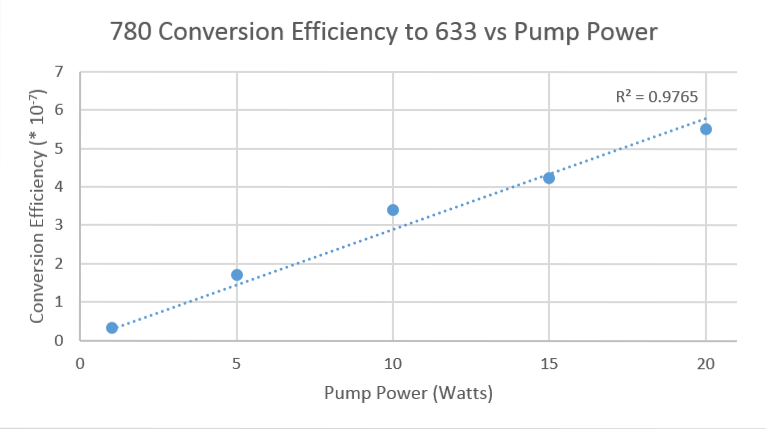
7/31/14
There's about 150 pW of noise on the lock-in even with all lasers and lights off. This is more than before, since I was able to easily measure a 60 pW signal. I'm not sure what caused the change. Maybe the old photodiode was less noisy and I just haven't looked at such small scales on the new one. It shouldn't be a problem if I'm generating nWs of 633, but maybe the generation is way down again since I haven't optimized everything after switching the 780 to a fiber. If I still can't see a signal today, I'll try switching back to the old photodiode initially.
Measured 58% transmission of 780 from a single set of the cavity window/mirror
Found a weak 633 signal using the old photodiode. Quickly improved it and switched back to the new photodiode (so that I could get accurate power measurements). The signal was now visible on the new photodiode. I thought for a long time I must just be missing the photodiode, but apparently the thorlabs one just isn't sensitive/quiet enough when the signal is in the pW range. I'll remember that for next time.
New efficiency measurement is [math]\displaystyle{ 5.5*10^{-7} }[/math] In addition to walking the 780 beam, I also slightly adjusted it's polarization and the focus of the a-sphere on the output fiber launch, both of which slightly improved efficiency.
Deniz can calculate the maximum theoretical conversion efficiency of 780 if we know the amount of 1064 and 1555 in the cavity. After a silvered mirror and a prism, I measured 0.55 mW maximum of 1064 when locking, and 0.50 μW of 1555.
The prism (Thorlabs PS853) has a listed transmittance of ~28% for both 1064 and 1555 and a silver mirror should be ~97% reflective at both wavelengths, so exiting the cavity there should be 2.0 mW of 1064 and 1.8 μW of 1555.
The cavity mirror transmits 32 ppm and 38 ppm of 1064 and 1555 respectively, so that puts the powers at 62.5 W and 47 mW inside the cavity.
7/30/14 Josh says the 1064 beam is closer to 1200-1400 at the ends, so the 780 beam should be pretty good. I'm trying to measure the power of the 633 beam again but am having difficulty. I can see 633 in the mirror, both right after the diffraction grating and at the end of the PVC tube, but I'm not able to get a signal off the lock-in amplifier. I'm using the same settings as when I originally found the signal. There is a lot of noise and also this doesn't seem to change much when I take out the 633 bandpass filter or when blocking/unblocking the 780 which is surprising since 780 and 633 should be the only signal modulated at 500 Hz.
7/29/14 I tried a variety of lens combinations again for a telescope, and adjusted the lens positions over a large fraction of the focal distance of the second lens, but they all failed to collimate the beam at the wall (~20 feet) better than just the a-sphere by itself. I've decided to go with just a single lens for now and if this doesn't improve the 633 generation efficiency enough, I'll maybe switch to checking other variables like gas pressure. Calculating the proper focal length for the lens doesn't seem practical since there is about 34 cm of propagation distance before the lens (a distance over which the beam diverges a non-negligible amount) and then 20 cm after the lens before the beam enters the cavity. Finally the cavity mirror will also adjust the focus somewhat. I modeled this setup with a spare cavity mirror and just tried different lenses to see what works best. A focal length of 400mm was a good compromise, giving a beam size of around 930 at the start of the cavity, 630 in the middle, and 1075 at the end. While the 1064 is 810, this is actually only at the center and is somewhat larger at the front and back of the cavity--these sizes for the 780 beam might be alright then.
7/28/14 Further measurements on Friday showed that the beam actually still diverged quite a bit after the telescope, to the point where it won't be useful. The performance seems limited by the laser/a-sphere which will not fully collimate out of the fiber. I'm switching out the 110 a-sphere on the output for a 230. It doesn't collimate quite as well, but with a shorter focal length, I'm hoping it will be smaller over a propagation distance of about 1 meter.
| Path Length from Lens (cm) | Horizontal Size (μm) | Vertical Size (μm) |
|---|---|---|
| 34 | 595 | 510 |
| 40 | 615 | 540 |
| 65 | 970 | 820 |
| 84 | 1380 | 1250 |
Looks like the first asphere was better over this distance range.
Looking at the fiber with the fiber scope, I saw that it was damaged. This explains some of the weird structures in the beam when looking at it against the wall and will maybe improve the generation efficiency of the 633. I changed to a 810 nm single mode fiber, which seems to work fine for 780. The beam quality if much better, although it still won't collimate very well. I tried a 150mm and 75mm lens again and looked at it against the wall, but the smallest I could focus it to by moving the 75 mm lens was still a couple inches. My best bet at this point might be to go back to a single long focal length lens, but I will make one more try tomorrow.
7/24/14 The camera was extremely temperamental. The XP computer in the other lab room would recognize it and work, but the laptop would not. I re-installed the software/drivers, which didn't fix it right away, but eventually I got it working. I couldn't say what I did. The upper USB port on the right side of the laptop worked for it though--some of them seem to give better luck than others. With the TA all the way up, the beam is way too strong for the camera to properly image, but I don't want to turn down the power in case it affects the beam size. I put in a 780 notch filter, which always it to be imaged without overloading at the shortest shutter speed and low sensitivity. I don't think the notch filter should affect the shape much, especially since the beam has already been filtered by the fiber and should be almost all at 780 nm. I turned the chopper off since it runs at a similar frequency to some of the shutter speed options and was interfering. The beam looks very Gaussian as expected.
Measurements are as follows, with sizes using the "13.5%" ([math]\displaystyle{ 1/e^2) }[/math] value:
| Path Length from Lens (cm) | Horizontal Size (μm) | Vertical Size (μm) |
|---|---|---|
| 18 | 730 | 695 |
| 34 | 470 | 510 |
| 40 | 416 | 420 |
| 65 | 885 | 925 |
| 84 | 989 | 1045 |
| 100 | 1360 | 1280 |
The beam is in the cavity and should be overlapped with the 1064 from about 22.5 cm to 97.5 cm. The 1064 beam is about 810 by 810 μm, so the beam is too big in some areas.
Following Jared's advice, I made a telescope with a 150 mm lens and a 75mm. By putting the 75mm one 225 mm from the 150 (f1+f2), the final beam should be fairly well columnated and smaller. This easily reduced the beam from around 1200 to 850 μm, which was very promising. I'll test more precise alignments and different lens combinations tomorrow. I'll have to rearrange the 780 optics again to accommodate a setup like this, but ti seems worth it if I can produce a sub 810 μm beam through the whole cavity.
7/23/14
I've been aligning the 780 TA to a fiber so that the output will be single mode and Gaussian. This was more difficult than I hoped it would be, but all the problems in the end seemed to be from the having the wrong aspheres for the fiber launches. I'm only getting about 20-25% power through the fiber. Around 40% should be achievable, but I'm not really concerned about power as much as conversion efficiency at this point. There's about 50 mW just before the cavity with the chopper on, so there should be about 34 inside. After re-aligning the 780 beam, I'm getting just under 3 nW unchopped power at the photodiode, giving a conversion efficiency of about [math]\displaystyle{ 3.3*10^{-7} }[/math]. This is higher than without the fiber, but not the big jump I was hoping for. Adjusting the polarization of the 780 helped with 633 generation a little. I'm guessing the main problem at this point is that the 780 isn't fully overlapped with the 1064. 633 generation seems much more sensitive to the 780 alignment this time, which suggests the beam is smaller (a good thing). We previously had a 150 mm -C lens to focus the 780 into the cavity, which didn't seem the best choice given that there is about 400 mm of path from it to the middle of the cavity. I replaced it with a 400mm -B lens, but haven't checked the beam size. Next steps should be measuring the beam size and seeing what can be done to reduce it and ensure the beam is smaller than the 1064 or at least focuses in the middle of the cavity.
7/18/14 The value that the lock-in displays is actually slightly different from what it outputs. When viewing the signal on an oscilloscope, the mean voltage better matches what I would have expected yesterday (about 8.6 V for a 2 V peak to peak square wave--closer to the 9.0 V it should be than what the screen shows). Looking at the output of the function generator on another oscilloscope revealed that the output is slightly noisy--this might account for the difference in the expected and measured values. I'm going to just assume that the lock-in is operating on square waves according to the formula from yesterday. It's certainly close.
The photodiode is definitely too slow for the chopper. The rise time is plenty fast, but it seems there is a fairly long decay time--the waves were asymmetric, with the first half looking good and the second half looking like an exponential decay. They got worse with increasing chopper frequency. I switched to a Thorlabs PDA10A, which has no problem even at 1000 Hz. At 633 nm, it has a listed responsivity of about .38 A/W.
Now I can compare the HeNe power measured by the power meter and the lock-in. The power meter read 199 μW just before the PVC pipe. I then took out the 780 notch filter before the photodiode and had the photodiode output to the lock-in and the lock-in output to an oscilloscope. The oscilloscope read 6.7 V. I had the sensitivity on the lock-in to 1 V, so using the formula from yesterday for offset square waves, the peak-to-peak voltage from the photodiode should be 1.49 V. Checking the photodiode on the oscilloscope confirmed this was accurate to about 5%. Then,
[math]\displaystyle{ P=\frac{V}{(.38 Amps/W) * (10^4 V/Amps)} = 196 \mu W }[/math]
With the .38 Amps/W as the responsivity of the photodiode and the [math]\displaystyle{ 10^4 }[/math] V/Amps is the transimpedance gain of the photodiode. The results agree! This is the power with the chopper on, so double it if we want the actual power that could reach the photodiode.
So for square waves generated from chopped 633 nm light hitting the photoiode with minimum voltage 0 and maximum A as read on the oscilloscope, the unchopped power reaching the photodiode is:
[math]\displaystyle{ P=\frac{A*Sensitivity}{(4.5*0.38 Amps/W) * (10^4 V/Amps)} = (5.85*10^{-5} W/V) (A*Sensitivity) }[/math]
I tested this again by cutting the HeNe power with an ND filter to 2.57 μW as measured on the power meter. Using the formula for the lock-in, I calculated 2.63 μW of power.
I measured the power of the generated 633 beam using this technique and found a typical unchopped value to be 5 nW. About the same value as before, but I'm much more confident in the calculation technique. This gives an efficiency on the order of [math]\displaystyle{ 10^{-7} }[/math], so the next steps should probably be better shaping the 780 beam since there don't seem to be many gains left to be made in alignment.
7/17/14
I'm trying to calibrate the chopper/lock-in system to get better measurements of the 633 power and make sure our conversion efficiency numbers are accurate. I cut the power of the HeNe beam with irises to 20 nW as measured on the power meter (filters might have been better so that the intensity is reduced too, but I couldn't find a good combination to get the power I wanted. It probably won't matter since there is a lens in front of the photodiode anyway). However using the lock-in and my previous procedure to convert photodiode signals to power, I calculated only 1.25 nW.
Jared and I have both thought that the visible power meter head has been giving somewhat high values (10% or so), so I'm skeptical of its readings. However, further investigation of the lock-in reveals the display signal is always multiplied by an additional factor of 10, regardless of the gain settings. Page 21 of the manual alludes to this, but I couldn't find a full description. I measured this value as closer to 9 though--I used a function generator to send in a square wave at 500 Hz with a max amplitude of 2V and a min of 0V, similar to the type of signal the photodiode should send in. With the gain setting on the lock-in as "1 V" or "1 μA", the output was 9 V. A 100 mV average value square wave gave 0.9 V.
Ok, the multiplicative factor of 9 is checking out more--it matters for the lock-in whether the input signal is a sine wave or square wave. For a sine wave, it singles out anything oscillating at the set frequency and gives the RMS voltage. For a square wave, it takes only the first Fourier component (2/π sin(ωt)) and then the RMS value (multiplied by [math]\displaystyle{ 1/ \sqrt{2} }[/math]). Page 31 in the manual is helpful. So for a square wave pulsed laser at 500 Hz like I'm sending in, the output voltage should be
[math]\displaystyle{ \frac{peak to peak* \frac{2}{\pi}}{(\sqrt{2}* sensitivity)} * 10 = 4.50 *\frac{peak to peak}{sensitivity}=output }[/math]
I've still been having trouble getting the lock-in readings to match the values I think it should have, whether I give it a signal from a function generator or from the photodiode. A 2 V peak-to-peak amplitude square wave should give a reading of 0.9 V on the lock-in [math]\displaystyle{ (4/(\pi*2^{\frac{1}{2}})) }[/math] and an output of 9 V for the extra factor of 10. Page 31 in the manual gives this as an example. However, I am getting closer to 0.8 V. Values for simple sine waves are off by about the same amount. This lock-in should be just displaying the RMS of the sine wave.
I also noticed that I am not getting perfect square waves from the laser/chopper/photodiode combo. While it works well at low frequencies around 40 Hz, at 500 Hz where I was running it the waves are distorted. This is likely because the response time of the photodiode is not fast enough. This should not affect optimization procedures, but it does mean that the Fourier component at 500 Hz does not have an amplitude factor of 4/π. I will either need to run the chopper slower if there is not too much noise at lower frequencies, or calculate a better value for the pre-factor before converting to an absolute power value for the 633 beam.
7/16/14
In addition to increasing absolute power of the 633 generated, we also want to improve the conversion efficiency. The 780 beam is larger than the 1064 in the cavity, so this will greatly limit efficiency. Maybe try a prism pair to reduce anisotropy or a fiber to make beam Gaussian? Power will be reduced, but efficiency should be higher.
From page 69 in Josh's lab book #1, the 780 notch filter transmits about 19% at 633. This seemed low and I measured it with the HeNe as 88%. It seems like the curve for the notch filter is incorrect and I probably should recheck the cavity window and mirror curves with the spectrophotometer at some point. For now, I'm just going to manually measure everything with the HeNe and 780 TA.
633:
Notch Filter: 88%
Cavity Mirror (spare): 77%
Cavity Window (spare): 79%
Both: 61%
Or 65% for the pair when measuring through the actual cavity (took the square root since the generated 633 will only pass through one pair). I'll use this value. 29% through entire path past cavity (pickoff is first element; grating is last element; 633 bandpass filter is in) or 22% with a 780 notch filter in. The power for the 633 fluctuates somewhat, so these are not super accurate. The chopper cut the measured powers almost exactly in half as expected.
So with the 633 bandpass filter and the 780 notch filter, .61*.22 = 13% 633 gets to the detector, or 6.5% with the chopper on.
For the 780 TA at 1W, with the chopper on there is 270 mW just before the cavity and 90 mW just after, so inside the cavity there should be 156 mW of 780.
I walked the 780 beam while ramping (a small 633 signal is still detected when ramping since it flashes at a relatively low harmonic of the 500 Hz chopper speed). Presumably finding the max power when ramping will be the same as when locking. Increased the signal to 5.8 nW at the detector (accounting for chopper--I'm always going to do this since we could turn the chopper off and have a 5.8 nW beam, it would just be hard to detect), which means 5.8/.13 = 42 nW in the cavity.
Our current efficiency then is 21 nW/156 mW = [math]\displaystyle{ 1.35 * 10^{-7} }[/math] (use chopper-on value for 633 since we use the chopper-on value for 780).
633 generation is very cavity mode dependent. As I scrolled the piezo and locked in different areas, the 633 produced varied by about a factor of 10. I saw up to 10 nW. The 5.8 nW value given earlier was one of the more typical ones.
Lasers are dangerous--we should set up a curtain around the computer and Wednesday afternoon lab laser tag should probably be cancelled.
7/15/14 Further 780 alignment optimizations have raised the 633 power at the photodiode to 1.9 nW (3.8 accounting for beam chopper). I put in a 780 notch filter right before the photodiode to make adjusting the 780 alignment easier--the scattered 780 at the photodiode changes when adjusting its alignment, which washes out a change in the 633 signal. Hopefully this will make changes in 633 easier to detect.
7/14/14
Power flickered today and the temperature controller for the TA shut off and the TA got to 40° C before we realized. It seems undamaged. The controller also shut off later again--maybe another power flicker, or is it broken? Keep an eye on it...
11:43 am I see something! I'm almost positive. Is champagne allowed in lab? What time does happy hour start at the library? When locking the 1064 beam with the 780 on, there is a noticeable jump in signal that is not present with the 780 off. Turning on/off the 780 changes the DC offset of the signal, but the jump when locking is about 10 times higher when 780 is on. The signal is clearly correlated with the lock.
Settings are as follows:
Gas Pressure: 2.515 volts
633 bandpass filter is in place before the diffraction grating
Oscilloscope scale is 20 mV (signal when locking jumps ~100 mV)
Chopper frequency: 500 Hz (chopper is outputing the frequency to the lock in--one of several variations I've tried including using the lock-in to set the chopper frequency and using a function generator to set both frequencies. Having the chopper in charge seems to be the most stable).
Lock-In: signal input (using only built in amplifier)-- I ([math]\displaystyle{ 10^8 }[/math]), time constant-- 1 sec, slope/oct-- 12 dB, sensitivity-- 50 μV, reserve-- low noise, filters-- off
Checked the power output on the TA and found it was only about 300 mW. Re-aligned the seed laser and the power is back to 1 W. This increased the locking signal, which comes to about 60 pW as measured the detector. Since the chopper is blocking the beam 50% of the time though, the effective power is 120 pW. There are other significant losses from optical elements as well--about 40% of the incident light on the grating goes into the first order at 633 nm (as measured with the HeNe), 93% for the 633 bandpass filter (measured with HeNe), 60% and 70% for the cavity window and mirror, 90% for the dichroic, and 3 silver mirrors and the cavity pickoff at 95% each. All together, this means that we are only getting 5.7% power at the photodiode, including the 50% reduction from the chopper. So inside the cavity there should be about 1 nW of 633.
I turned down the current to the TA, reducing it's power by a factor of 3. This reduced the measured locking signal by a factor of 5, which is not linear but at least the measured power correlates with the 780.
We're very convinced the signal is 633. After briefly playing with the 780 alignment, Josh and I increased the measured signal to .5 nW. There are likely many more gains that can be made. Suddenly we lost the signal in the afternoon for no clear reason. Eventually after realigning the HeNe and photodiode I was able to find it again, but it was back to the lower level of around 60 pW. Apparently the setup is very sensitive to a variety of factors, but this it to be expected if the signal is indeed from 633 generation.
Things to try this afternoon--remove photodiode and make sure 633 flashing is visible with current alignment, remove 633 filter--offset should change, but locking signal shouldn't change much (check how much 633 it should pass), move 633 filter to the front of the detector--does this reduce DC offset when turning 780 on/off?, turn down 780 power--does locking signal decrease linearly?
7/11/14 Spent the last 2 days setting up the beam chopper and a lock-in amplifier for it. It works very well and after sending the HeNe through 2 irises I could easily measure it 1 nW. I thought I was seeing a signal at one point that only appeared when locking when the 780 was one, but I haven't been able to replicate it yet. It's difficult to optimize the settings on the amplifier since I can only lock the 1064 for a second or two at a time. Is there some way I can do it while ramping instead?
7/9/14 Testing the 633 filter showed it lets through about 90% of 1555. We want to determine that most of the scattered light is 1555 like we think. So far we know the signal appears only when locking 1064 and that the cavity window cuts the signal by a factor of 5. It also seems to be only scattered light because blocking the path from the grating does not affect the signal.
Evacuated the cavity and re-aligned 1064. Couldn't see what we've believed to be the 633 beam (as expected) although I couldn't figure out how to re-overlap the 1064 and the 780 beams (usually we use the generated 807 beam, which passes through the dichroic mirror). Hopefully I'll be more clever tomorrow. The 1064 alignment was only marginally more than for a typical morning though, so I don't think it would be moved so much that the 780 wouldn't overlap enough to generate 633 if gas were in the cavity. I found that the signal to the photodiode when locking was actually much higher now--about 20 nW. This happens whether 780 is on or off, so it can only be from 1064. This may suggest it is not 1555 as we suspected, although there is much more 1064 generated when locking with no gas in the cavity (I measured about 200 mW exiting the cavity when locking today), and 1555 might still dominate when there is gas.
Putting the cavity mirror in front of the PVC pipe drops the signal by a factor of 50 to .4 nW (was I off by a factor of 10 when I checked with gas in the cavity? I don't think so, but maybe recheck).
Since the signals when locking don't seem to be from 633, the .4 amps/watt value I've been using for the photodiode to calculate powers is probably incorrect. For 1064, it is closer to .25 (so powers are actually higher), and it is unrated at 1555. Still, the relative power drops are useful.
Removing the cavity mirror and completely blocking the PVC opening with a book still let through about .25 nW, so actually when the cavity mirror is in place about as much light gets to the photodiode from the PVC pipe as from through the cloth. Maybe it's time to make a better case for the photodiode. Still, since the book cuts down the signal by a factor of 80, most of the light does enter through the PVC pipe opening. Does the cloth transmit significantly more of either 1064 or 1555?
So at least some of the locking signal is from 1064, and some is likely to be 1555 as well. The cavity mirror helps and other filters probably would as well, but it still seems the best option is to use the beam chopper.
7/8/14
Pumped down the cavity in case some nitrogen had leaked in over the last few weeks. Re-added deuterium to about .3 atm. Noted that the .5 nW signal when locking the cavity is present even when the path from the diffraction grating to the photodiode is blocked. The locking signal looks about the same size whether or not the path is blocked, although the offset is different. There is no noticeable difference with the 780 on or off. I tried blocking off part of the optical table at beam level, but this didn't affect the .5 nW signal. It seems that the signal is almost definitely due to scattering. The 633 bandpass filter we use is not rated at 1555, so it may be letting through significant amounts of light at this wavelength. This could explain why the signal was present when locking even with the filter in place if the signal is from scattering. Putting in the cavity window in front of the PVC pipe reduced the locking signal by about a factor of 5 both with the beam path to the detector blocked and unblocked.
7/7/14
Installed a flip mirror for the HeNe, following Nick's advice. Switching between HeNe and 780 beams is much easier now and I am more confident in the alignment of the 780. Using a mirror as we have previously done, I was able to see 633 past the PVC pipe just before the lens, so it is almost certainly hitting the photodiode given that it is getting through the pipe and that I centered it on a photodiode with a lens using the HeNe as a guide. Still though, there is no clear change in signal between having the 780 on or off when locking the 1064. Josh, Deniz, and I tried to come up with explanations as to what could cause this and alternate methods to make the measurement (See Things to Try). We thought maybe a second order beam from the diffraction grating could be angularly close to the 633, but using the grating equation with G=1800 lines/mm, no second order diffracted light should exist above 475 nm, so that seems unlikely. Two 89 THz shifts and one 8.9 THz shift could produce light in the 630 nm range, but this would probably be a weaker signal than the .5 nW we are seeing.
7/4/14 It still seems that there is no difference in signal whether the 780 is blocked or unblocked, and there is a clear signal of around .5 nW when locking the 1064. The HeNe is not staying very well aligned--I hoped only a horizontal adjustment would be necessary, but it seems unscrewing it from the pedestal creates too much of a vertical change.
7/3/14 Had some difficulty with the 1064 beam today, see 1064 laser notes. I also realized that even after getting the HeNe laser going through the cavity and hitting the diffraction grating, there was still a fair amount of play with the mirror walks which ultimately could move the beam at the photodiode by a couple inches. The generated 633 beam might be missing the detector then. I put two irises in the 780 beam path after the cavity and separated by a couple feet of path length. After lining up the iris to the 780 beam, I swapped in the HeNe and used its mirror walk (which is independent of the 780 path) to align through both irises and then put the photodiode and lens in this beam path. Hopefully the generated 633 beam will be overlapped with the HeNe path now and is hitting the photodiode. Maybe try using a very large diameter lens before the photodiode so there's more tolerance?
7/2/14 Decided to try propagating the beams across the lab instead of making a PVC maze in hopes of getting good spacial separation. We borrowed a breadboard from the optics lab and aligned the HeNe through a PVC pipe about 15 feet away from the diffraction grating. The beam then goes through a lens and onto the photodiode mounted on a translation stage. There is still a signal when locking the 1064 beam, even with the 780 blocked. The signal does not change unblocking the 780 when the 1064 is not locked, so there is no 780 beam getting to the detector. Whatever it is seems to be from the 1064 or a sideband as we previously believed.
7/1/14 Realigned 1064 to the cavity and 780 beam after they had been left alone for a few weeks, and got 633 visible again by eye through the flip mirror. Re-overlaped the HeNe beam with the 780 path so that I can see where the generated 633 beam should go. USA is out of the world cup.
Business School/Vacation
6/13/14 We set up a diffraction grating over the past two days (G=1800; reflective in visible light region; borrowed from Saffman group), which gives better angular separation between wavelengths than the prism. Using the grating equation,
[math]\displaystyle{ Gm\lambda=sin(\alpha)+sin(\beta) }[/math]
(page 22 in Newport Diffraction Grating Handbook), 780nm and 633nm should be separated by about 18.6°. We overlapped a HeNe (λ=632.8 nm) with the 780 laser path, and then used this to figure out where the generated 633 should be. We set up a 1 inch flip mirror for viewing by eye and had the photodiode behind it. This worked very well and we were immediately able to see the 633 in the mirror, which was aided by the fact that it was much smaller than the 4 inch mirror we used before and we could set up the irises using the bright HeNe signal. We could still not see a definitive signal for 633 with the photodiode though, although we are confident we are hitting it or are extremely close. We mounted the photodiode on a translation stage, which we will try adjusting next.
There was scattered light getting to the photodiode , which is mostly 1064 or one of the generated sidebands, since there is an offset on the photodiode signal that changes while adjusting the 1064 beam power. At its worst, we saw 1-2 nW, and this dropped to a few tenths of a nW after better covering the photodiode. There was also a change in signal corresponding to ramping and locking the 1064 beam, even with the 780 off. The 780 also caused a slight offset on the photodiode, but a much weaker one than the 1064. We're going to try making a non-reflective container to put the photodiode in to get more isolation. Otherwise we'll go with a long path through PVC pipes, which shouldn't be too difficult using the HeNe.
6/11/14 We aligned once more with the camera today, and also noticed that the waveplate after the 780 TA was not set optimally to match the polarization of 1064, which would reduce 633 generation efficiency. Fixing this and getting a better alignment of the 1064 beam with the cavity today let us see 633 through the prism again, with about the same level of brightness as previously. We could still not see it through the fiber, but this is likely just a coupling problem so we aren't concerned. We looked at the signal from the photodiode after the prism, and also a pickoff from the 780 TA and found them both to be very correlated with the cavity piezo movement. The 780 seed laser still seems stable though. We also found some correlation with the prism photodiode with only the 1064 beam on, so 1064 or a sideband must also be getting through to the photodiode.
The power fluctuations in the 780 TA are small and we don't think they are a problem beyond the difficulty they cause in detecting the 633 signal. We're going to ignore them for now and try to better isolate the 633 signal. We're switching out the prism for a diffraction grating and are going to use two PVC pipes in a "V" shape. Since there's only scattered light getting through and not any beams besides 633, this should greatly reduce noise. We're also going to remove the lens before the photodiode, since this is focusing scattered light too, and instead put the photodiode on a translation stage.
6/10/14
Re-aligned the 780 and 1064 with the camera, but this did not make the 633 visible through the fiber. We re-walked the beams into the fiber, since it was fairly misaligned after yesterday's adjustments to the isolators. We still couldn't see 633 flashing though when ramping the cavity and with filters in place. The alignment to the prism was off after re-aligning to the fiber, so we set up a separate walk to the fiber and prism. We can't see any 633 now, but hopefully decoupling the fiber and prism will make it easier to optimize the signal once we find it again.
6/9/14 We realized just before DAMOP that we were getting feedback to the 780 laser. A lot of it seems to be coming from the cavity mirror, since the frequency/mode of the 780 seed changes when adjusting the cavity piezo. After retuning the isolators, the seed laser appears stable both on the OSA and wavemeter when adjusting the cavity piezo. We noticed there is still some change in signal on the photodiode when adjusting the piezo, and this occurs even with the 1064 off, so it seems there are still small back reflections affecting the 780. This is a much smaller effect than previously though, and since it isn't causing the laser to jump frequencies, we think it shouldn't be a problem.
The 633 light was much weaker today than when we were working on it before the conference. It was still visible through the prism, although dimmer, and it was unclear whether it could be seen through the fiber.
DAMOP Twenty-Fourteen!!!!!
Poster (PDF PowerPoint)
5/23/14
The last few days were spent trying to improve the 633 signal and better isolate it. We used a Thorlabs PDA36A photodiode and pushed it right up against the fiber, but could only get a very weak signal. However it did seem to correspond with locking the laser. The laser locked well enough to try walking the fiber connection and the signal was improved, but eventually it was discovered that the 780 beam was blocked at the source. This means that some other light was getting to the fiber, even past all of the filters we had set up. 1064 seems a likely candidate. We added in an old cavity window, which reflects almost all 1064, realigned the 780 beam and found a signal we believe comes at least mostly from 633. We also switched to the much more sensitive PIN 5DP Photodiode and SR570 Preamplifier combination. While the previous signal was responsive mostly to adjusting the fiber coupling and showed little response to the 780 beam alignment, this signal was responsive to both. We were able to improve the signal by adjusting both the fiber coupling and 780 alignment. We also tried using a power meter, and while the results were not entirely clear, we believe we might have seen a signal of a few tenths of nW when locking.
We wanted to be more sure that the signal we were looking at was entirely 633, which can't be done with our current method even with numerous filters in place. We instead sent the cavity beams through a prism and aligned an approximately 2 foot long piece of PVC pipe and a small iris until we could only see the 633 beam through it by eye. Further adjustments greatly reduced the amount of scattered ASE that was previously visible. We then put in a 30mm -B lens at the end of the pipe and lined it up to the power meter. Measuring with the power meter proved too difficult even when covering the setup and blocking most external light to the room, but using the preamp and photodiode, we could detect a signal. There was some background noise, likely from light leakage, but when locking the laser we saw spikes between 100-300 mV from the photodiode. At 633 nm, the photodiode has a sensitivity of about [math]\displaystyle{ 0.4 }[/math] [math]\displaystyle{ Amps/Watt }[/math]. The preamp was set at [math]\displaystyle{ 10^9 }[/math] [math]\displaystyle{ V/Amp }[/math]. Calculating the beam power, we found the 300 mV signal to be 0.75 nW, which was consistent with our previous observations, although we expected this to be somewhat higher now that this was not coupled through a fiber.
Next time maybe try removing filters to reduce 633 losses, since we will spatially separate it from the other beams with the prism.
5/20/14 We continued to try to measure the 633 beam using the OSA and a power meter. We still couldn't detect anything, and the power meter measurements put an upperbound on the power in the nW range. The 780 seed laser hadn't been staying single mode very well, which could be reducing 633 generation or spreading it out to nearby wavelengths. We decided to try to fix this before continuing the search for 633. We tracked the 780 problem down to ASE feedback from the TA getting through the isolator and to the seed laser. This was eventually solved (see 780 laser notes). We're hoping this will increase 633 generation, and the nW power upperbound might no longer be accurate. We will look using the OSA and power meter again tomorrow and also using a photo-diode with high gain, which might be more sensitive. We swapped the ________ photodiode and unplugged the 1555 reflected signal, which we will try to remember in a couple weeks when it doesn't work.
Bread time was especially good today. Josh added one banana to the mix, which seemed to result in a slightly more flavorful and substantially moister bread. Nick was notably agitated by having a pineapple cored on his desk, but settled down once it became apparent the mess wouldn't be too bad.
5/19/14 After initial alignment of 1064, the 633 beam could easily be seen when ramping the cavity without any adjustment. It seems very repeatable, but also suggests that the power isn't close to being optimized yet since there was no noticeable difference in brightness after having a weekend to drift. We spent most of the day trying to increase the 633 beam power so that we can see it on an OSA. First we worked on the 780 alignment and adjusted it while looking at the 633. A full "beam-walk" was too difficult without some sort of numeric measure of 633 power, but by only adjusting the vertical and horizontal of one mirror we made the 633 substantially brighter. At one point, the 633 signal disappeared (well after the walking process) and moving to different cavity modes didn't help. I'm not sure why this happened, but this was solved by slightly translating and rotating the prism and then adjusting the beam blocks for the 807/780/1064 beams. This was an easy process to get the 633 beam back, which is encouraging.
We also doubled the power of the 780 as measured directly after the TA (see 780 laser notes). We still couldn't see a signal on the OSA though, even with lots of averaging and with the beam locked. Looking at the coupling fiber when ramping the cavity, however, we could clearly see the 633 beam flashing above a constant background of 780. Putting in an 780 notch filter and a 633ish bandpass filter (borrowed from 1st floor John), we now have what seems to be a flashing 633 signal with very good contrast (i.e. against very little background). The fact that this filter works makes it even more definitive that what we're looking at is 633. We hope that this will be easier to optimize and finally detect with the OSA. It's confusing that the 633 signal is so visible even through the fiber and when not looking directly at it--is the eye that sensitive to 633, or could we be having equipment issues?
We also looked at the 780 beam on the OSA after the TA and saw that there is a large spread in wavelength due to the amplified spontaneous emission (ASE) of the TA. (The 780 region contains far more power than the other regions though--the signal looks somewhat Gaussian with a delta function in the middle). This explains why were still see light from the 780 beam even after two notch filters. The 633 filter should help.
5/16/14 1064 laser was notably better today--easier to align, better peaks, and less prone to drift. We slightly translated and rotated the prism until the 807 beam coming out seemed more defined. It looked much better than the previous day, but this might be due to the improvement in the 1064 beam. We built a fort (what's took Jared so long with his?) to block most external light in the lab and blocked the 1064 and 807 beams from the prism, as well as the small amount of 780 that was getting through the notch filters. Any 633 should have greater angular separation from the other beams than the 780, so we were careful to only put the beam blocks right to the edge of the 780 so as to avoid blocking any 633 that might be generated. We then used the camera to overlap the 780 and 807/1064 beams on the 1064 side of the cavity. This worked well today and was an easy process once we made sure no beams were clipping.
We then looked for 633 generation by eye by sending the prism output to a mirror and then perpendicular off the table at eye level. We still wore goggles as they should have little effect on a 633 beam but would help with 780 or 1064 if something went wrong. We immediately saw a red beam, but believe it to be a small amount of 780 internally reflecting in the prism and scattering. Further searching revealed another red beam (perhaps of slightly different color) that flashed when we were ramping the piezo. It was highly angularly dependent, but once we found it the first time and knew where to look it was fairly easy to find again. This beam also changed intensity when we changed the 1064 or 780 beam intensities. Additionally it disappeared when turning off the RF signal (we were using the old locking circuit and had it set to ramp so that it would exhibit peak broadening), and would disappear when moving the cavity piezo to a "bad" position. This is the exact behavior we would expect from a 633 beam, but we couldn't find a signal with the OSA yet, which will be our next step. We want to try slightly adjusting the 780 alignment as well to see how this affects the candidate 633 beam intensity.
Jared and Nick were somewhat impressed when we showed them the 633 beam, but Nick was quick to point out that he had a green laser while ours was only red. Blocking all external light in the lab along with the whirring from the machines creates a very spooky atmosphere, and Josh and I were quick to note to the potential marketability of the setup. We are thinking of turning the lab into a full-fledged fun house style attraction. Follow us on twitter (@HauntedLaserLab)!
5/15/14 1064 laser still seems somewhat different than usual, but aligned more easily than yesterday. It was still more prone to drift than was typical. Attempted to overlap 780 and 1064/807 beams on the 1064 side of the table using the camera in two locations. However, the beams were clearly not overlapping on the 1555 side after this, so we did a visual alignment on both sides of the cavity. We later realized the 780 was slightly clipping and we were aligning to a scattered beam with the camera. The 1064 is too dim to see on the 1064 side past the dichroic, so we aligned to the 807 since they should be in the same place. We added in two 785 notch filters before the prism to make it easier to look for 633 generation. The 780 beam was slightly clipping the prism (and so any 633 might be also), so we adjusted the prism. The very defined 807 sidebands we saw yesterday were worse afterwards and the number of sidebands we saw didn't match the number seen with the OSA when immediately switching between the two. No beams are clipping on any optics as far as we can tell, so the angle must not be quite right with the prism and we will try to find a better position tomorrow.
Got ice cream for employee appreciation day. Josh, Nick, and I were more than willing to wait in the 10 minute line for unlimited free ice cream, but Jared and Zach quickly left. "Captain No-Fun" now redirects to Jared's page. Nick believed sherbet and sorbet to be synonymous, which was proven incorrect.
5/14/14 1064 laser was more difficult than usual to align, was very prone to drift, and only locked passably well. Gas pressure is about 0.3 atm. Josh says it's been like this for a few days, although it seemed to show slight improvement in the afternoon. We set up a mirror on the 1064 side so that we can send 807 from the cavity to a fiber launch or a prism. Despite having the dichroic as one of the coupling mirror to the cavity, on the Saffman group's OSA, we could see all 3 beams with rotational sidebands (should only by 807, but 1064 and 1555 were about the same power as 807 instead of much stronger). It seemed there were some only vibrational modes too, but we haven't tried to repeat this yet.
Putting in a filter dropped the 807 signal by about 10 dBm and made the 1064 and 1555 no longer visible on the OSA, however 1064 could still be seen very faintly with the IR viewer after the prism. We're confident we're seeing pure 807 after the prism due the to OSA signals and since we can clearly see 1064 and 807 diverge. Sending the 807 about 8 feet away to the wall, the separation between 807 and 1064 is about a foot. Depending on the mode, we see 1-2 or 5+ sidebands on 807 over about an inch.
Froze snack banana for 10-15 seconds in nitrogen. Ice clearly formed on the peel, but the interior was only somewhat cold. Will try for 30 seconds next time.
780 Laser Notes
Tapered Amplifier (TA) is a 3 micron chip 1W 780 nm from Eagleyard Photonics. TPA-0780-01000-3006
Specified maximum rating is 3 amps of input current when seeded, but should be able to output 1W with 2 amps.
There should be about 2 mW of power going into the TA, although 5-10 mW should be fine if the output power still isn't at 1W with the current around 2 amps.
8/4/14 See daily-log entry for alignment procedure to maximize 633 generation.
6/9/14 Re-retuned isolators both directly before and after TA. Feedback seems reduced. Re-aligned to isolators and TA in the process, seed laser is now set to 70 mA, with about 3.3 mW going to the TA. At 2000 mA, the TA now outputs about 1000mW.
5/20/14 Seed laser for the TA was very multi-mode. We eventually tracked the issue down to feedback from ASE due to the TA. We tuned the isolator and brought feedback down from a few hundred μW to about 20 μW, and the seed laser is now very stable. It should be possible to reduce this further with additional tuning, but it doesn't seem necessary at this point. We also reduced the TA current from 2000 mA to 1800 mA to reduce ASE, and had to increase the seed power. Seed current is now at 70 mA and the waveplate was adjusted to give about 6 mW to the TA. Output power from the TA is now around 900 mW.
5/19/14 Having difficulty seeing 633 nm generation from the 780 TA beam, but realized that the TA can actually take more current than we previously thought. Increased current to 2 amps and adjusted waveplate to give about 3.3 mW of seed power. Current for the seed is still at 65 mA. Output from the TA increased from about 500 mW to 1000 mW.
5/15/14 Increased 780 Laser current from 43 mA to 65 mA and adjusted the waveplate to continue sending 2 mW to the TA and the rest of the power to a fiber. Locked the waveplate at the right position--do not adjust without decreasing laser current.
1064 Laser Notes
Threshold tests Usually get around 100 μW at 20 mA of current. A small adjustment of the diffraction grating (~a quarter turn total) will usually show little adjustment in output power, except for a narrow spike and drop off near the optimal grating feedback setting.
8/27/14 Retuned temperature loop on the Vescent laser controller. We had been having current fluctuations for the past few weeks but this seemed to solve the problem.
7/3/14 Threshold test seemed off yesterday and was very off today. It took about 26 mA today to get to 100 μW and the laser was very multimode. Adjusting the grating position ultimately resolved the problem. The current reading on the driver is sometimes fluctuating, usually just by .1 mA, but sometimes by up to 5 mA. This doesn't seem to be causing any problems right now, but it is unclear why this is happening.
1555 Laser Notes
Diode is a QPhotonics QLD-1550-40S-AR. See specs here and datasheet here
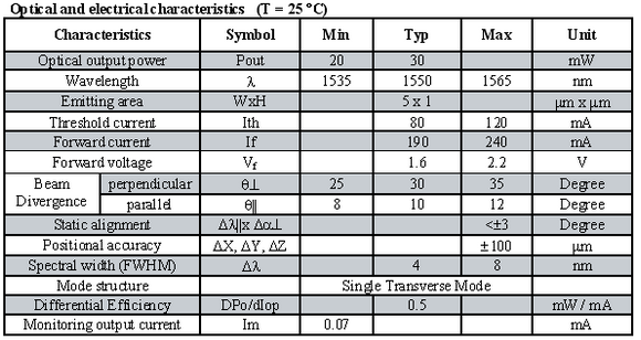
9/24/14 Changed the 1555 diode for a new one of the same model. Performance seems better. I've been running the threshold tests at 0.5 mW, which will usually jump to around 1.3 mW with only a single narrow spike. Driving current is ~42.5 mA
9/2014 When trying to set up the 1555 amplifier after a couple months of inactivity, everything was not surprisingly pretty misaligned. I was getting only about 2 mW to the amplifier, and so sometimes the power would drop too low to properly seed it when I would adjust the grating. Eventually I re-aligned everything including the isolator and the EOM. For the EOM I just maximized the power through it, and checked with a photodiode and RF analyzer that I was still getting a signal at 20 MHz (the beat frequency between the original and shifted beam). I'm getting closer to 3 mW now at the amplifier, but this is still less than I remember it being when Josh and I were working with it a few months ago. I'm only seeing about 13 mW right after the grating. Could there be a problem with the diode? Is the feedback just very off?
Also remember the amplifier power meter doesn't go above 3.52 mW. It's done this since before my time.
Long-Term Ideas
- TEC on EOMs
- Get higher power isolators and increase pump/stokes powers. Alternatively, expand beam before isolators since we are only pushing the intensity limit, not total power.
- Use laser diode instead of TA for the 780 beam? Thorlabs makes a 400 mW single mode one. Probably get as much power in the cavity and there would be way few optics that could become misaligned. The beam would also likely be better collimated and a telescope could work to shrink it.
- Use an extra beam cube/waveplate to dump the "bad" part of the 1064 beam. Still about .5 W comes through when the waveplate is set to give the minimum. Does this polarization just not help much or does it hurt performance?