David Notebook: Difference between revisions
| Line 24: | Line 24: | ||
==Daily Log== |
==Daily Log== |
||
'''3/16/15''' |
|||
Major findings of the last month: |
|||
We got the interferometer set up again and, surprise, there's no linewidth narrowing from the ebay mirrors. So I switched back to the layertec mirrors (the two curved ones--again it's unclear why it doesn't work well with one curved and one flat). The linewidth looks around 20 KHz, which is at the limit of what the interferometer can measure, so the narrowing is potential less. Some sources suggest you need a substantially longer fiber delay than the coherence time of your last (like 6 times as long) but I've seen it quoted that being equal is fine too. It's clearly narrowing substantially though. |
|||
The layertec mirrors never locked very well. I attributed this to bad slow feedback for a while (all the piezo would ever do is rail). It seems like the actual problem though was etaloning between the fiber launch and some other element. Essentially the pre-locking cavity peaks were inside a larger envelope of some much lower finesse cavity. This explains the strangely high sensitivity the walking mirrors seemed to show. I put an isolator in which mostly fixed the problem. It seemed to substantially reduce the error signal and transmitted signal though--way more than the 20% or so lost through the isolator. I'm unsure why since it the shape of the beam shouldn't be affected. But the cavity locks okayish for now--upwards of 10 minutes when working well. Improvement can certainly be made, but for now I'm working on the Raman cavity since the basic features I want from the pre-locking cavity are there (much longer lock times than the Raman cavity and substantial linewidth narrowing). |
|||
Little luck with locking the Raman cavity. I've been working on making a slow-feedback locking circuit (see Zach's description under equipment list) but am still having a few issues. I borrowed on of his completed circuits though and haven't had luck, but still have a few things to try. I had thought our old slow box was broken since the power supply always went a little crazy when I plugged it in, but I realized today that the manometer is actually drawing way more current than it should. Plugging the slow box in just always pushed the power supply over the edge. The -15 V line was actually running closer to -11 V. I'm not sure how long this has been going on. I've just unplugged the manometer for now since I don't really need it when I'm just operating under vacuum. |
|||
The low pass filter after the mixer on the PDH setups seems to be greatly lowering the error signal. Like most things, I'm not sure why. I'm taking them out for now on the grounds the added signal is pretty much too high frequency to do anything in the servos, and any detrimental effect it has is probably greatly outweighed by the decrease in SNR. |
|||
I'm getting worried this isn't going to work. I guess that was a risk when I started this, but I really thought if we got the laser linewidth on the order of the cavity linewidth we could lock with just slow feedback. I don't really see how that's different from what Nick does with the SHG cavity. At least I've learned a ton, and I've really only been trying something that might potential work for a day or two. I can always table this whole things for a bit and come back to it in a few months. I think I might be starting to become frustrated with it to the point where I'm not working effectively. Probably in another week or so I'll start trying to set things up to modulate the pulsed orange laser, which is something I think I can do. |
|||
'''2/11/15''' |
'''2/11/15''' |
||
Got very poor locking by using the old 1555 slow feedback box on the Raman cavity while the laser was locked to the low finesse cavity. I was having trouble sending two error signals to the Vescent box since they seemed to interfere with each other, so I'm trying this method for now. Having the laser locked to the low finesse cavity seemed to help stability with the Raman cavity, but not for transmitted power. I think we're not getting any or enough linewidth narrowing, so I'm going to swap the cavity mirrors again. I think the problem with the Layertec mirrors wasn't that they were too high fiensse, but that we weren't impedance matched (I still don't think we understand that very much though). So I'm going to use the two curved mirrors which should be pretty identical and presumably more reflective than the ebay mirrors. |
Got very poor locking by using the old 1555 slow feedback box on the Raman cavity while the laser was locked to the low finesse cavity. I was having trouble sending two error signals to the Vescent box since they seemed to interfere with each other, so I'm trying this method for now. Having the laser locked to the low finesse cavity seemed to help stability with the Raman cavity, but not for transmitted power. I think we're not getting any or enough linewidth narrowing, so I'm going to swap the cavity mirrors again. I think the problem with the Layertec mirrors wasn't that they were too high fiensse, but that we weren't impedance matched (I still don't think we understand that very much though). So I'm going to use the two curved mirrors which should be pretty identical and presumably more reflective than the ebay mirrors. |
||
Revision as of 04:02, 17 March 2015
Things to Do/Check
- Measure beam size for isolator intensity limit
Check the RF generator with the giant screen--is it actually broken and putting sidebands on or is it set to modulate the primary signal?not broken
- Upload power meter data
Questions for Deniz
- What is the limiting factor in the pump/stokes power we input. Why only 20W--only about 12W for stokes makes it to the cavity.
- When under vacuum, does it matter whether the cavity is cooled? Surely alignment will be slightly different, but just for getting the lock working well it would be easier to not have to add nitrogen all the time and to not have the cavity slowly warming up. No in principle, but it would probably change cavity mirror couplings and I don't want to have to adjust those and then change them back
- What's with the noise on the locking signal and DC error? Is that a problem? Fixed it--RF generator problem
- How much power do we typically transmit from 1555 when under vacuum? 1W absolute best. 700-800 mW is pretty good
- Why do the locks drop in power--it doesn't usually lose a lock all of a sudden, but it will continuously decrease more or less (way more rapidly with the 1555) until no more power is being transmitted?
- Do we need integral and differential gain? Isn't error signal linear?
- Thoughts about why adjusting the phase delay line didn't seem to produce much effect on the error signal? Who knows. Ask Josh. This could be important, we should try to figure it out
Daily Log
3/16/15 Major findings of the last month:
We got the interferometer set up again and, surprise, there's no linewidth narrowing from the ebay mirrors. So I switched back to the layertec mirrors (the two curved ones--again it's unclear why it doesn't work well with one curved and one flat). The linewidth looks around 20 KHz, which is at the limit of what the interferometer can measure, so the narrowing is potential less. Some sources suggest you need a substantially longer fiber delay than the coherence time of your last (like 6 times as long) but I've seen it quoted that being equal is fine too. It's clearly narrowing substantially though.
The layertec mirrors never locked very well. I attributed this to bad slow feedback for a while (all the piezo would ever do is rail). It seems like the actual problem though was etaloning between the fiber launch and some other element. Essentially the pre-locking cavity peaks were inside a larger envelope of some much lower finesse cavity. This explains the strangely high sensitivity the walking mirrors seemed to show. I put an isolator in which mostly fixed the problem. It seemed to substantially reduce the error signal and transmitted signal though--way more than the 20% or so lost through the isolator. I'm unsure why since it the shape of the beam shouldn't be affected. But the cavity locks okayish for now--upwards of 10 minutes when working well. Improvement can certainly be made, but for now I'm working on the Raman cavity since the basic features I want from the pre-locking cavity are there (much longer lock times than the Raman cavity and substantial linewidth narrowing).
Little luck with locking the Raman cavity. I've been working on making a slow-feedback locking circuit (see Zach's description under equipment list) but am still having a few issues. I borrowed on of his completed circuits though and haven't had luck, but still have a few things to try. I had thought our old slow box was broken since the power supply always went a little crazy when I plugged it in, but I realized today that the manometer is actually drawing way more current than it should. Plugging the slow box in just always pushed the power supply over the edge. The -15 V line was actually running closer to -11 V. I'm not sure how long this has been going on. I've just unplugged the manometer for now since I don't really need it when I'm just operating under vacuum.
The low pass filter after the mixer on the PDH setups seems to be greatly lowering the error signal. Like most things, I'm not sure why. I'm taking them out for now on the grounds the added signal is pretty much too high frequency to do anything in the servos, and any detrimental effect it has is probably greatly outweighed by the decrease in SNR.
I'm getting worried this isn't going to work. I guess that was a risk when I started this, but I really thought if we got the laser linewidth on the order of the cavity linewidth we could lock with just slow feedback. I don't really see how that's different from what Nick does with the SHG cavity. At least I've learned a ton, and I've really only been trying something that might potential work for a day or two. I can always table this whole things for a bit and come back to it in a few months. I think I might be starting to become frustrated with it to the point where I'm not working effectively. Probably in another week or so I'll start trying to set things up to modulate the pulsed orange laser, which is something I think I can do.
2/11/15 Got very poor locking by using the old 1555 slow feedback box on the Raman cavity while the laser was locked to the low finesse cavity. I was having trouble sending two error signals to the Vescent box since they seemed to interfere with each other, so I'm trying this method for now. Having the laser locked to the low finesse cavity seemed to help stability with the Raman cavity, but not for transmitted power. I think we're not getting any or enough linewidth narrowing, so I'm going to swap the cavity mirrors again. I think the problem with the Layertec mirrors wasn't that they were too high fiensse, but that we weren't impedance matched (I still don't think we understand that very much though). So I'm going to use the two curved mirrors which should be pretty identical and presumably more reflective than the ebay mirrors.
Good locking settings for the ebay mirrors are: 1st integrator: 100 Hz 2nd integrator: 1 KHz-1MHz or off differentiator: off aux gain: who cares, can lock without it prop gain: 4.0 turns--sometimes turn up to get it to lock then turn back down a bit to stabilize.
2/5/15
The eBay mirrors ended up working. I'm using two curved ones with R=75 cm, so the waist is in the middle of the cavity now. The size was only about 10 microns different, so I basically just moved the cavity forward 5 cm, and what do you know--huge transmitted and reflected peaks. I'm guessing it's better because the mirrors must be very close in reflectivity, but it's weird because the impedance matching equations (see the python script) suggest that it shouldn't be a huge deal assuming the reflectivities differ by a couple tenths of a percent (seems likely for any cavity mirrors). Maybe there was something about the plano-concave configuration? We don't quite understand something here, but sometimes you just gotta move on.
With a bigger reflected signal it wasn't too hard to get the laser locking to the cavity. It was easier to lock to non 0,0 peaks. Even though the signal was smaller than the 0,0 mode ones, they were more stable in transmitted power, which made it easier to lock to and the lock more robust. I don't want to send to much power to this cavity though since we need most for the fiber amplifier, so for now I'm locking to the 0,0 mode but I might switch back. The cavity seems much more responsive than before. When I adjust the MML, I can see the cleanness of a FSR change. It looks about as good as the Raman cavity.
The lock still isn't perfect, but it's much better than the Raman lock--I've gotten a lock maintained for ~1 hour, which is already good enough. I think I can probably still improve it. In addition to the locking circuits, putting the cavity in a padded tube might help damp low frequency noise which seems to be the dominant error signal frequencies.
So now is the hard part of the whole locking 1 laser to 2 cavities thing. There's a lot of ways I can see to do this. We generate a second error signal from the Raman cavity--we can try sending this to a lockbox and feeding back just to the cavity piezo (maybe the laser line is sufficiently narrowed from the low-finesse cavity). We could send both error signals to one lockbox (it turns out you can add two signals just be using a splitter backwards! Who knew? No one in lab, that's for sure). But that could be tricky to try to get it to lock to two things at once, even though the frequencies are pretty different. After locking one, trying to adjust the DC offset to get the other signal locked would probably disrupt the first lock. I could probably lock the low-finesse cavity with just the fast feedback and then try using the aux servo output on the same vescent box to lock the Raman cavity--this has the same issue though of having to adjust the DC offset, but would have less competition with the fast feedback.
What I think is most likely to work is to use a second lockbox and feedback either directly to the laser diode or combine error signals and send both to the current driver (I don't see any advantage of feeding to the diode, and that would be difficult/invasive to setup). I tried the combining error signals and feeding back to the current driver (slow-feedback to the separate piezos today). One problem I had was with the RF signals. At first I used a second RF generator for the Raman error signal, but I noticed a lot of noise. I eventually realized it was at 5 Hz and tracked it down to the fact that the RF generators aren't super accurate and the signals differ by about 5 Hz even when they are both set to exactly 50 MHz. The problem got a lot better when I reduced the frequency of 1 by 5 Hz, but it was still a little off and I didn't have the resolution to improve it more. So it seems like all the signals need to come from one RF generator. But without some crazy combination of splitters, I can't send the same power to all components. I eventually upped the power of the 1064 RF generator to 13 dBm (this is now the normal power that should be run at), split the output to send 10 to the Raman error signal, which leaves 10 to be split into two 7 dBm signals for the EOM and low finesse locking signal as usual. But this means that the Raman cavity error signal is getting 10 dBm instead of the usual 7. It probably doesn't really matter, but this is different than before. Maybe I can find an attenuator that'll work?
Anyway, once that was all worked out I wanted to try the double locking thing. In short, it didn't work yet but it seems like it could be possible--I had two error signals going into the current driver and nothing crazy happened and both Vescent boxes seemed like they were almost locking. I was having trouble with the low-finesse lock, which I think it just because the RF power is probably slightly different, and more importantly the summing signal thing (backwards splitter) probably introduces a phase delay that I haven't properly accounted for. I want to check with RF or function generators tomorrow and see if I can figure out how much it delays things. Hopefully there's no dispersion because I don't know how I could fix that.
It would also be good to check the linewidth when locking to the low-finesse cavity once new Zach gets the interferometer running.
1/22/15
Still haven't heard back from Layertec. Thorlabs says they can do it, but it'll be ~7 weeks, so I'm holding off on that for now. Deniz says Lambda Research is usually pretty fast. I requested a quote from them but haven't heard back yet. Zach found some mirrors on eBay that don't give a ton of info, but seem like they might work. I ordered them and hopefully with that we can make something happen.
1/20/15
I put an arrow on the backpolished E03 mirror pointing towards the side that was facing upwards in the packaging. I think this is the "back" side that is less well polished. The mirror didn't seem to help the signal strength though, and in fact made it worse. I flipped the mirror around too in case I got it in backwards, but I didn't notice any change. The problem now is probably that it is poorly impedance matched because the reflectivities are so different, which apparently is a thing. I updated that python program to account for this--we're probably only getting a few percent of the full height of the reflected signal for resonance dips just because of the impedance, so that's probably the issue now. I'm seeing if Thorlab can make us a custom curved mirror (2 E03s would give a finesse of ~800) and I'm talking to Layertec about making a pair in the 2000-3000 range. We want the highest finesse we can get away with that will still be easy to lock and stay locked, but we're not sure what value that will end up being.
1/15/15
Zach and I both kept having trouble getting much transmitted signal and any reflected signals. We thought maybe we weren't mode matched well, but we'd both tried a few times and that didn't seem to be it. It was also possible that the laser linewidth was much bigger than the cavity linewidth. I made a python thing here that calculates the power of an incident beam that is coupled into a cavity based on the spatial and frequency profiles. The cavity mirrors listed a selectivity of about 99.98%, which would give a finesse of around 16,000. The cavity linewidth is just the FSR/finesse, so it would be ~95 KHz, so with our ~500 KHz linewidth laser, and even very rough spatial coupling, we should still have been getting some power. We thought maybe the radius of curvature of one of the mirrors was wrong, but we took out the cavity mirror and found that it focused a collimated beam at ~25 cm, which would give the correct R of 50cm. In retrospect this probably wouldn't have mattered as much as we thought--the spatial coupling curve is quite forgiving.
Eventually we thought maybe the finesse was higher than we thought, and I measured the reflectivity of the plane mirror and found it to be about 99.998%. It's safe to say we'll never be buying German made optics again! Assuming a similar reflectivity for the curved mirror, this would give a finesse of 160,000. The linewidth would be very narrow then, and we'd only get about 2% power even ignoring spatial coupling. This is likely the issue. We ordered a back polished E03 mirror from Thorlabs which we'll swap in. That has a reflectivity closer to 99.6%, which would bring our finesse down to a more manageable 1600.
1/12/15
I briefly was getting the laser to lock for a couple second a few times over the last couple days, but couldn't improve it much. I think I'm seeing pretty good cavity peaks now though--stable and what appear to be a couple free spectral ranges. I want to figure out what kind of piezo is on the laser though, so I can know how much voltage change should give a free spectral range (so I know I'm not way zoomed in on some higher mode stuff).
I can't see anything for a transmitted signal with the PDA10A, without using an amplifier which would reduce the bandwidth too much. I don't see dips on the reflected signal, so this might be part of the locking problem. Maybe I'm not mode matched well enough and aren't getting enough power. I thought it a different lens/cavity position configuration I was seeing peaks on the PDA10A, but that seemed like it had worse mode-matching. Well it was pretty spot on in one dimension, but not even close in the other. Right now it should be pretty close in both, but maybe the last little bit matters a lot and so it was still better overall before. I'm going to re-profile the beam tomorrow and see how close I am and maybe see if I can improve it.
1/8/15 Nick had the really good idea that my peaks might be so unstable because I wasn't ramping at a high enough frequency (James from Saffman said this can be a problem), and I don't think I was at a high enough amplitude either. I switched to the external ramp and it looks much better now. I think I'm seeing a few free spectral ranges with not much non-0,0 modes, but the reflected signal is very weak (I can't really see it). I'm going to try locking though and see if I can get anything. I'm just using the vescent box for the 1064 cavity beam, so here are the current locking parameters for when I need that to work again:
First integrator: 10 KHz
Second integrator: off
Differential: 500 KHz
Differential gain: 22 turns
Auxiliary servo gain: 4.5 turns
Proportional gain: 3.3 clicks
Phase delay line: ~9'2"
Winter Break Update
Pre-stabilizing cavity Wow, I've really let this get out of date. We've moved forward with the pre-stabilizing cavity idea. We needed to buy a lot of optics, but realized we could get away without another EOM by just picking off after the EOM on the main experiment. Even when we feedback to the same current driver, the error signals shouldn't interfere with each other, because their frequency components ultimately depend not just on the EOM modulation frequency, but on the cavity length too.
Zach made some cavities with a finesse of a few thousand. They're made of a special steel that has a very low expansion coefficient, and so they should be pretty stable. I didn't realize mode-matching was so important for cavities, but it is and so I had to learn a lot about that and Gaussian beam optics. Nick has a helpful MATLAB problem for calculating the coupling parameters to the cavity, which I've uploaded here. I also found this youtube video pretty helpful and the few chapters about lasers in the Pedrotti optics book.
The cavity is 10 cm with one plane mirror and one with a 50 cm radius of curvature, for a and . I used the spinning camera for measuring the Gaussian beam parameters to figure out what kind of lens was needed to mode match. With the initial beam, I could only match the x or y component unless I got some cylindrical lenses or a prism pair, which seemed like too much work, so I decided to couple to a fiber to get a mostly circular output. I found the correct mode matching lens to then by an f=750mm about 10 cm from the fiber output and then another 55 cm to the cavity. The lens is on a 1-d stage for small translation adjustments.


I was having difficulty finding a signal from the cavity for a while, but looking at the reflected signal rather than the transmitted proved useful. The reflected signal is made with a quarter wave plate and a beam cube to provide some isolation from the back reflections and to allow the power to be adjustable. The center of the cavity is at a height of ~3.375 inches, so I marked that on the fluorescent stone and walked the beam to that height before putting the cavity in. Then by overlapping the horizontal back reflection with the incident beam, I could usually see peaks on either the reflected or transmitted photodiode. The reflected signal looks very weird though--very jagged without any obvious periodic dips, but it seems like it has to be result from the cavity transmission since it only is visible with the ramp on. The transmitted signal looks more normal, except it is extremely unstable--just barely touching a mirror without even adjusting it will make the peaks jump around, and they fade in and out just over a few seconds by themselves. I've gotten it aligned where it looks pretty good except for how unstable it is. Maybe I'm actually locking to a of axis-eignemode or whatever and these are just the biggest peaks I've seen so far and I'm mistaking them for a 0,0 mode free spectral range. Maybe the cavity mirrors are slightly misaligned.
We thought the instability might be caused by the non-angle polished fiber I was using, so I switched that out but it didn't seem to do anything. It doesn't seem to be back reflections feeding back to the laser either, since looking at the laser on the spectrum analyzer shows nothing weird even when the cavity peaks are drifting in and out. The power reaching the cavity is pretty constant too, so I don't think it's the fiber being weird.
That mostly brings us up to today
We got a new IR scope from the surplus store. We were having trouble with it for a while, but we traced it back to just a bad connection with the battery case and swapped it for the case from the old IR scope. It works great now.
We were thinking of trying to modulate the output from the pulsed laser before we broaden it with the PCF as a preliminary experiment while we're still figuring out all the PCF stuff. The wavelength would be too close to the pump beam though, so the optics wouldn't work for us to be able to pass it through the cavity. We thought we could maybe frequency double it first and then send it in, but Deniz thinks we'd need about 10 mW of green to do it, and I'm not getting more than a few hundred μW from the doubling crystal. I tried changing the temperature of the crystal some since that's supposed to affect the wavelength it responds to, but that didn't seem to do much. I might try expanding and more tightly focusing the beam to increase the intensity if I get stuck on the cavity stuff.
12/3/14
Been swamped with classwork lately, but a few lab things worth noting.
I've pretty much concluded the 2 photon experiment can't be done with the current setup. The way Josh did it previously was by broadening the cavity peaks and then tuning the frequency differences with the laser piezos. He could then scroll to a different broadened peak, which would be about 200 MHz away. We're at higher pressure and locking makes the frequency jump a lot and in a pretty unpredictable way.
I think we need to pre-stabilize the lasers with a low finesse cavity. This will 1). make locking to the high finesse cavity much easier. The lasers would potentially stay locked for a lot longer so that we could just focus on tuning them rather than keeping them locked. And 2). Give us another way to tune the laser frequency--we could lock to different peaks of the low finesse cavity to change frequencies by its free-spectral range.
Another way we could maybe do the experiment would be if we could recreate the peak broadening behavior. We used to turn off the slow feedback box and ramp the cavity or laser piezo. When the piezo hit the resonance position, the fast feedback would keep it resonant for a bit (even as the piezo kept moving), resulting in a broadened cavity peak. This doesn't work with the vescent box even when we unplug the piezo, which I think is because the minimum frequency the the current driver responds to is different from our previous setup. I'm waiting to hear back from vescent about this issue. In the mean time I tried making a high-pass filter so that I could manually adjust it (well, I couldn't decrease the minimum frequency, but I could effectively increase it though). I wanted it to be able to filter out frequencies below a couple hundred Hz, but it didn't really do anything though, which might be partly because I used a pot with wire coils which probably has a big impedance, but from talking to people it also sounds like you need to use an active filter at low frequencies. I probably should just buy something then, but I'll wait until I'm more convinced that will help.
The manometer also seems like it got calibrated somehow, since it was saying the cavity was pumping down to about 20 times lower pressures than it usually does and that seems unlikely. I unplugged it and reconnected it, and it gave more normal values, but it's a little bit offset from where it used to be, probably by 10-20 mV. That shouldn't really matter since most of the pressures we're at are in tenths of volts and I can't really get those accurate to 10 mV anyway.
There was also an issue with the 1064 laser giving unstable wavelength readings. Like fluctuations of about 500 MHz every second (I mean, it stayed withing about 1 GHz over pretty long times, but just bounced around within that). This turned out to be because of the multimode fiber we were using. The frequency wasn't actually doing this, but the fiber was supporting extra spacial modes which was confusing the wave meter. Using a single mode fiber gives readings stable to 10s of MHz, which makes more sense. I couldn't get enough of both 1064 and 155 coupled with a single mode fiber, so I might need to order one that will work better, or just keep in mind the deal with the 1064 one.
Vescent also put an updated manual for the servo controller up, and it has some helpful info. There are apparently some secret switches you can only get to by taking the side panel off, a few of which do interesting things. One secret switch lets you set the box to ramp in "master" mode rather than "slave". Previously we had to input an external ramp, which we could then turn on or off and adjust the amplitude of. There's nothing really wrong with this that I can see, but it's just another piece of equipment and nest of wires to complicate things. I switched to the internal ramp, but I might need to change back if we ever get the peak broadening working again, since you can't ramp while locking with just the vescent box. There's also a switch to change it so that the vescent box will only output a positive ramp. This is good since we don't want to put a negative voltage to the piezo. We normally have to manually put an offset on it each time and then take it off at the end of the day (since we don't want to leave a voltage on the piezo). This also means there's not really a reason to output to the Thorlabs piezo controller. All it basically does is serve as a buffer to prevent negative voltage going to the piezo, amplifies the signal, and lets you make small adjustments. The internal ramp seems strong enough, so I've switched to just using that for now. I'm not sure if it's better that way, but I'm hoping maybe it will make the lock better since it kind of has more direct control over the piezo now without having to go through another device with its own gain and phase delay.
11/19/14
Once again, 1555 locked at 0.05 atm with minimal adjustment. This is a very good sign. I've got a new procedure for getting 633 back if the 780 gets misaligned. No cameras or IR viewers required and it's quicker and easier--put a fair amount of gas in (maybe 1 V or so) so that there aren't many spacial modes without 633 and there's a lot of it if alignment is good. On the 1064 side of the cavity, turn down the power and use a card to overlap the 1064 and 780. Then turn the power back up, lock the 1064, and on the 780 side of the cavity use the other alignment mirror to overlap the transmitted 1064 with the 780. Repeating this 2-3 times will get 633 back depending on how badly aligned it was. Optimal alignment will change slightly when you switch back to whatever pressure you were working at, but it should still easily be detectable and so is not hard to fix.
I'm getting closer to being able to do the 2 photon experiment. Both lasers have been locking pretty well at this pressure, 633 is easily visible with just the 1064. Now I just need to practice tuning the laser frequencies and figure out how to keep them that way even when they lock and jump frequencies.
I think pre-stabilizing them with reference cavities would help a lot, but I'll keep trying this for a bit and see if I can make it happen without them. There's still probably a few weeks before the Moglabs wavemeter is ready, and the pulsed laser is still not set up either, so it's not really holding much up.
11/18/14 Hot damn! 0.05 atm might be the magic pressure. 1555 locked again today with only small adjustments. Good settings seem to be integrator at 5 kHz, differentiator at 500 kHz (this definitely seems the best setting for all pressures). Differentiator gain seems to give a trade off between power and stability. Prop. gain around 3.75. Optical feedback at 1.4 V (I didn't realize the scale on the oscilloscope had changed--I've normally been doing around 400 mV, but this actually worked well with different gain settings. Maybe more optical feedback, less gain is better if I can get it to work).
11/17/14
I've been mostly still trying different locking settings. The 1555 is amazingly inconsistent and I'm not sure what's really changing day to day. Both locks work better under lower pressure though, so I've been trying to find a good compromise between getting 633 generation and easy locking. 0.38 V (0.05 atm) seems like a good spot. There's 633 at a fair number of cavity modes, and it's easily visible in mirror or on the photodiode. I'm going to stick just at this pressure for a while and maybe I'll be able to learn more about locking just at this pressure.
It also occurred to me that we might be able to run the lasers are higher power. The limiting factor is the isolators, but the 1064 one is rated for 60 W and 500 W/cm^2. We're obviously under 60 W, and I think our intensity is ok too. At 30 W of input, we would need a beam larger than 1.4 mm. I'll measure it when I get a chance. The isolator's aperature is 4.7 mm, so we could always expand the beam and re-collimate it after. That would be a lot of trouble, but we could increase our single beam conversion efficiency by 50%.
11/5/14 I'm not sure what happened, but something must have gotten bumped and the 1555 was completely misaligned--no cavity peaks or anything. It was good practice at setting that back up at least. The best way seemed to be to turn the power way down and look at the incident beam and reflected beam with the card and try to overlap them in two places. Then I moved the transmitted photodiode and took off all the filters/covers and put it right at the transmitted side of the cavity. Using the HeNe was helpful for making sure the photodiode was pretty much aligned to where the 1555 beam would come out. Turning the power all the way back up and making small adjustments with the walking mirrors usually got some very small peaks which could them be optimized.
Locking is still inconsistent. It's not too bad under vacuum, but with gas settings that work one day don't work as well another, and the higher the gas pressure the worse it seems to be. I lowered the pressure only about 0.57 V (about 0.07 atm), and was able to achieve pretty good locking--~150 mW transmitted, with the best locks stable for a few minutes. I was able to simultaneously lock with 1064 too (the bandpass filter helped), and I think I can still get sideband generation at this pressure, although the 780 was misaligned and I'm not able to see any 633. Hopefully after fixing that, I'll be able to get some 633 generation and have consistent locking settings and performance at this pressure.
Current successful settings for 1555 lock at 0.07 atm:
course gian: 4 clicks
fine gain: bit over halfway
first integrator: 10 kHz
differentiator: 500 kHz
optical feedback: ~300 mV
11/3/14 The 1555 lock works pretty well under vacuum when it works. Getting it to work is a problem. It seems to need different settings everyday, so apparently is very sensitive to small fluctuations. When it is working well, I've gotten between 800-1000 mW that is pretty stable in power (often less than 20 mW fluctuations), that can last for over a minute. Again the necessary settings seem to differ everyday, but usually a good lock can be achieved just by adjusting the optical feedback, proportional gain, and auxiliary servo gain. The first integrator is set at 5 kHz, the differentiator is set at at 500 kHz (gain set somewhere in the middle), and the second integrator is off.
Try optical feedback somewhere in the 100-600 mV range, and the proportional course gain at 4 clicks (the necessary settings for these two seems to be loosely inversely proportional. Sometimes the piezo voltage will max out (158.6 V), which usually means the gain is too high. Sometimes lowering the proportional gain helps, but this can also cause the laser current feedback gain to be too low, so try adjusting the auxiliary servo gain independently. Sometimes it will still lock fine at very high power with the piezo maxed out, which is confusing. Maybe it is still actually making small adjustments, which just aren't visible, or is the piezo actually doing very little?
Also it basically refuses to lock by adjusting the cavity piezo and you have to use the DC offset on the lock-box instead. Who knows?
The necessary locking settings are very different even at just 0.1 atm. I have the first integrator all the way down at 2 kHz. The proportional gain and optical feedback I've had to adjust all over the place. I had it locking well briefly and was getting about 150 mW, but lost it pretty quickly when trying to optimize it. The window of "good" settings seems much smaller with gas. The laser piezo is especially difficult--with the auxiliary servo gain too high (or just the overall gain too high), it maxes out the piezo, but when just a bit lower it doesn't seem to do anything. In fact I would get locking signals that were reminiscent of ramping with just the fast feedback on back in the old days (suggesting that the slow feedback wasn't doing much).
I did finally figure out where I would get weird signals from the transmitted 1555 photodiode (sometimes negative, sometimes positive when locking; the signal would quickly jump up and then fall down to center around zero even with the output power fairly constant). They seemed like symptoms of AC coupling even though everything as set to DC, but it turned out the photodiode is premade to AC couple. That's slightly annoying because it makes it hard to tell how good a lock I have without measuring it, but a new photodiode it expensive (we don't have any extras at this wavelength), so I'll make do for now.
10/29/14
I don't think the cavity leak is a problem for now--don't usually run it at less than 0.1 atm, or 760 mV, so the leak is a pretty small fraction of that. I got both locks working individually, but when trying to lock together the 1064 beam seemed to interfere with the 1555 lock. I think it's the generated 807, since there would only be interference in cavity modes where 633 was being generated (and so 807 was also). This is probably fixable with just a notch or bandpass filter. I also noticed that the error signal on the 1555 was very noisy again, at least compared to the 1064. Not the 1 kHz noise I was getting for a while, but just generally very staticy. I'm not sure if this is new or I just didn't notice it before. I eventually tracked it down to the low-pass filter, which doesn't seem to be doing anything. Switching it with the 1064 one fixed it. It's not locking well now, but presumably I'll have to retune some parameters now that there is a working low-pass filter and that there is gas in the cavity.
10/24/14
I think the cavity has a small leak. At room temperature, it will pump down to ~12 mV, but will be up at ~30 mV by the next day. This is probably too small to be a big deal, but I should check with Deniz.
10/22/14
I'm not sure what was going on with the laser driver, maybe a loose cable? I haven't had that problem again in the last week. I got the 1555 lock working better and got to about 600-700 mW of power. However, when it was locking well and the noise was low, the transmitted signal looked like a sine wave with a frequency of 1 kHz. Clearly the noise I was having was causing a problem. It turned out that the RF generator was putting side bands on the signal at 1 kHz. I swapped RF generators which seemed like it should help a lot. I got up to ~850 mW, but I think there is more optimization to be done since the phase delay was changed. The lock is pretty inconsistent from day to day, but I decided to put it aside and get the 1064 working again and then add gas before trying to optimize the locks much more.
The 1064 was much easier to get locking, although the transmitted power is low. Only around 70 mW after playing with most of the parameters fairly extensively. I'm not sure why it is lower, but the lock is pretty stable.
I'm still confused as to why I don't see the changes in error signal that I would expect when I change the phase delay. There doesn't seem to be much difference on both the 1064 and 1555. This is definitely something to focus on because it seems like it could be having a big effect on the lock.
10/15/14
I tried to follow the various signals through all parts of the PDH circuit. I made slight adjustments here and there, and most notably added some BNC length to change the phase delay on the local oscillator. I also turned off the integrator on the lock-box and so was just using the proportional gain. The error signal should be linear near resonance, so do we even need differential and integral adjustments? I saw the best performance yet, with powers over 300 mW and fairly consistent.
I also saw a lot of weird behavior today. Ramping was very inconsistent, and it was hard to see if the laser was aligned even when I knew it was close and I should see some peaks. The oscilloscope near the cavity would show very little or no signal and sometimes the other one would show much more. It seemed more than just scaling, but a difference in signal to noise ratio. They are getting the same signal that is just split and the oscilloscope settings were comparable. I also didn't see the changed in error signal I would have expected when adjusting the phase delay length by half a wavelength (~1.9 m) (see the figure on page 32 of Green's thesis--everything looked like the pi/2 and 3*pi/2 plots, no matter how much cable I changed). I'm also still seeing noise on the error signal and DC offset channels. It seems different everyday. It's only present when the RF is on, but today there was a lot in the 20 Hz region (yes, Hz) on the DC offset channel. I still don't know what the cause might be and if it's a problem.
The weirdest thing by far was the current driver starting oscillating somewhat again, by maybe 1-2 mA. It's don't think it's bad temperature tuning again, because the temperature was staying within tenths of mK to the setpoint and I adjusted the setpoint too in case there were any weird resonances. I wanted to repeat the threshold test, and I couldn't turn the current down below 100 mA. At the lowest setting, that was what it output. Turning it off and on and unplugging the servo connection eventually got it lower, but then it would just start creeping back up without me adjusting anything. I checked with a power meter and the laser powers were consistent with the current value that was displayed.
10/9/14
I tried to track down where the noise was coming from. The DC error output on the vescent box only is noisy when it's connected to the error signal and the RF is on (doesn't matter whether the laser is on and there is actually an error signal). The full height is about 15 mV of noise. I checked the laser diode output using a photodiode and the noise doesn't seem to be coming from there. Most likely seems the RF amplifier in the circuit, although the low pass filter isn't cutting this as much as I'd think either. I tested the amplifier by itself though and it didn't show any sidebands, which would have been the obvious cause. It does have signals at integer multiples of the input RF signal, but those are all around 10 db lower. I checked the same amplifier on the 1064 setup and it showed similar behavior. The vescent box on the 1064 also shows similar noise with, although slightly less, so maybe nothing is broken and this has always been there.
10/7/14
Ordered 2 HeNes from Ebay so we can return the ones we've been borrowing from the optics lab. I've been wondering if maybe the amount of optical feedback isn't right for the 1555 locking circuit. I was able to get kind of a lock with only the first integrator on (20 kHz). Then I adjusted the optical feedback and then the proportional gain. The best performance seemed to be between 2-3 V optical feedback when the circuit isn't locked. It's currently set at 2.5V, which will give some locking with the proportional gain course knob 2 clicks up and the fine gain most of the way up.
I tried switching to the current 1064 slow lock (the old 1555 lock--i.e. the one that says 1555) (the 1064 is broken :( )) still with the vescent for the fast lock. Performance was still bad--I'd got a consistent "lock" with only power of a few mW transmitting from the cavity. The lock is still very "fuzzy"--not really a jump up in signal but rather the whole signal looks very noisy. I noticed that the DC error output on the vescent box is noisy, with a signal at very close to 1 kHz. The error signal seems noisy too.
10/1/14
Diode performance seems good on the OSA too. The peak from the threshold test was single mode and stayed single mode when I increased the current up to the operating value. When trying to set up the locking circuit, it would only occasionally go multi-mode and would quickly return to single mode when I turned down the amount of feedback (previously this would generally require re-scanning with the grating). I never had to touch the grating after the initial threshold test. By the end of the day, I had it locking using just the proportional gain and the first integrator on the Vescent box. The lock would quickly start falling but jump up again before disappearing entirely. This sustained for ~1 min, which is better than I've ever seen. The transmitted power was ~100 mW, which I think is lower than we had previously, but I'll have to look through Josh's notes. I think this will get better when I work with the optical feedback and the other integrator and differentiator. It was so much easier trying to improve the lock since the laser would stay single mode. Much more power is getting to the fiber amplifier too so it never shut off due to low power.
9/25/14
Ran threshold tests with the diode today--performance seemed good! Better than I had previously seen and better than what Josh had described. There are still multiple peaks at low power (although over a much smaller range than previously) and with the power up to ~0.5 mW (without well adjusted feedback), there is a single very clear spike in power (from ~0.5 mW to 1.3 mW) when adjusting grating position.
I'm not sure whether the old diode was bad, or if it was just the process of completely re-aligning this new one with the grating that ultimately improved performance. If it was the re-alignment, I think park of the trick was changing the horizontal grating adjustment to close to the middle position--maybe we were at too extreme an angle before to get good feedback. If we need to adjust the wavelength later it might be better to do what we can with temperature before moving the grating too much.
9/24/14
I've continued to have 1555 diode problems. Threshold tests were showing many small peaks of similar power. These individual peaks were generally single mode, but as I increased the current it went multi-mode well before reaching operating power. Deniz thought this was indicative of a failing diode, although Josh says this is consistent with the normal behavior he's observed (but that maybe it has never been working correctly). I tried re-collimating the laser and also moving the diode in the housing and re-tuning the grating and collimation. Neither of these procedures helped.
I decided today to change the diode before spending more time with a possibly bad diode. I was using the soldering iron at only 500 degrees to avoid possibly damaging the diode from heat, but this made it very difficult to solder a good joint. Eventually I changed to 550 and the process was easy and didn't seem to heat up the diode too much. The new diode works, although I haven't looked at its behavior closely yet. It might be worth trying to change the polarization since this can affect how much feedback goes to the diode and maybe would improve performance.
9/16/14
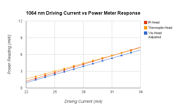
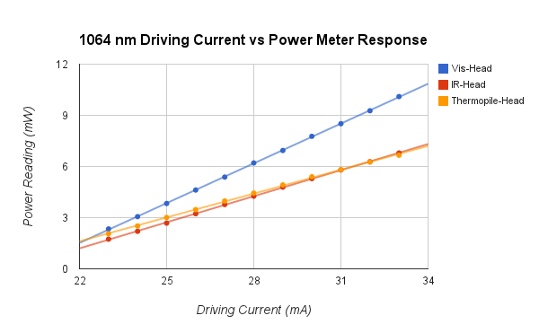
After looking at the power meters, the visible one definitely does not read 1064 nm accurately. The short story is that its values should be multiplied by 0.62. Graphs are here and here, full data is here. This makes the theory agree better with the experimental data, although the experiment is still low.
I've been continuing to work on the 1555 laser. The power has been dropping low enough that it sometimes turns the amplifier off, so I finally just re-aligned everything. See 1555 Laser Notes for more detail. I got the power somewhat higher, although it still seems low, so I wonder if the diode is having problems or if the feedback is very off.
9/11/14
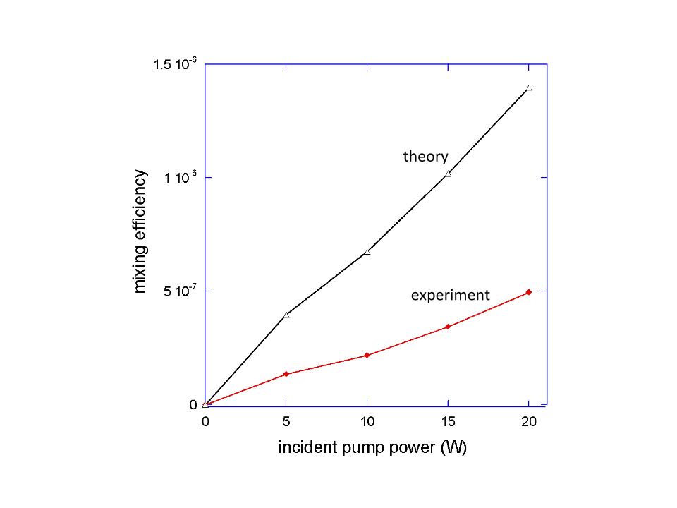
Jared and Zach noted at group meeting today that they get pretty different readings using the visible power meter head for 1064 then when they use the IR one or the thermal one (which agree well with one another). Additionally it gives significantly different readings when set ~1064 vs ~1050, which suggests it's not well calibrated near the end of the it's range. I used the visible power meter head I used to measure the 1064 beam power for the recent 633 data, so I should check and see just how much the power measurements differ compared to the other power meters. Hopefully it's a constant offset or fixed percent and we can adjust the data accordingly. Deniz did a preliminary analysis and made a theory curve. It's about a factor of 2.5 higher than the experimental data. There are still a few effects to account for that might lower the theory, and accounting for the 1064 power measurement issue will undoubtedly affect things too.
Here is the tentative graph though.
9/9/14 Still trying to get the 1555 to lock using the vescent box. It's very hard to keep the diode single mode--are these diodes just very sensitive, or is it not feeding back properly? Talk to Deniz. I'm reading a lot about locking--Josh's thesis is helpful, as is the original PDH paper. I noticed that on the the reflected 1555 signal is saturating the photodiode. I adjusted the ND filter closest to the photodiode from 1.0 to 1.5. This signal strength is adjustable with the waveplate/beam cube right before the photodiode, but it seemed like it was dumping a lot of power into the little fluorescent stone thing and I smelled burning (I might have imagined that though).
9/8/14
File:633 Conversion Efficiency Raw Data.xlsx
9/4/14 Previous table is just raw data and doesn't include adjustments for optical losses of stokes and pump. See data File:633 data.xlsx for adjusted version and with useful statistics. Josh has been gone starting this week. Very sad, although productivity is at an all time high. I've got classes again which means less time in lab though. I've spent the week mostly doing a bit of data analysis and trying to get the 1555 beam up and running again--I want to see how much that affects 633 generation if I can simultaneously lock 1555 and 1064. It took about a day to re-align the 1555. I could tell at some point I was getting a small signal on the photodiode, but it was so mis-aligned it was hard to optimize it at all. Eventually I moved the photodiode just past the transmitted 1555 side of the cavity and lined it up with the HeNe (which is a reasonable marker of where the 1555 should be if it's making it through the cavity. Moving the photodiode reduced a lot of the optical losses and I took off the ND filter. I was still getting a small signal that was hard to optimize, but looking at the ramping signal simultaneously proved useful. I knew a useful scale for 1555 peaks would fall within half a ramping period, so by adjusting the scale and then 1555 alignment I could eventually see peaks and optimize as usual. Not only was it very mis-aligned the but the oscilloscope settings were really off so I wouldn't have been able to see much anyway. I'll try to remember that for next time.
1555 is aligned now, although not locking. I'm trying the vescent box right now and hoping I can get that working, although I might have to switch back to the homemade boxes as before.
8/28/14
| Pump Power (W) | Transmitted Pump Power (mW) | Transmitted Stokes Power (mW) | Lock-in Reading (V) | Inner-cavity 633 generation (nW) | Conversion Efficiency (*) |
|---|---|---|---|---|---|
| 20 | .47, .63, .58, .50, .50, .54, .77 | 3.1, 2.8, 2.3, 2.6, 2.7, 3.3, 2.8 | 1.4, 1.8, 1.5, 1.4, 1.6, 1.3, 1.8 | 19.06, 24.51, 20.42, 19.06, 21.78, 17.70, 24.51 | 4.50, 5.79, 4.82, 4.50, 5.14, 4.18, 5.79 |
| 15 | .58, .55, .52, .49, .38, .35, .51 | 2.04, 2.24, 2.86, 3.05, 2.10, 2.35, 2.20 | 1.1, 1.2, 0.9, 1.0, 1.1, 1.3, 0.9 | 14.98, 16.34, 12.25, 13.62, 14.98, 17.70, 12.25 | 3.54, 3.86, 2.89, 3.22, 3.54, 4.18, 2.89 |
| 10 | .41, .35, .49, .43, .57, .50, .43 | 2.15, 1.20, 2.30, 1.50, 1.10, 1.60, 2.00 | .75, .6, .7, .8, .5, .6, .8 | 10.21, 8.17, 9.53, 10.89, 6.81, 8.17, 10.89 | 2.41, 1.93, 2.25, 2.57, 1.61, 1.93, 2.57 |
| 5 | .40, .50, .41, .50, .45, .43, .25 | .97, 1.28, 1.30, 1.10, 1.30, .90, .70 | .4, .44, .4, .5, .5, .3, .4 | 5.45, 5.99, 5.45, 6.81, 6.81, 4.08, 5.45 | 1.29, 1.41, 1.29, 1.61, 1.61, 0.96, 1.29 |

780=73 mW
8/27/14 Some relevant files:
Zach's analysis of the pulsed laser
I contacted Vescent about the laser controller problems we've been having, and it turned out to be an issue that would arise when the PID settings for the temperature controller weren't quite right. I retuned it and it's working much better now.
Replaced the 400 mm lens that focuses the 780 before the cavity with a 500. Had to completely re-align the 780, but 633 generation is higher again with an efficiency of ~ I ordered a 750 mm lens from Thorlabs which might work better too. There are definitely still gains to be made from having the 780 better collimated/focused, but I think it's good enough now to take the data we want.

8/26/14 Replaced the deuterium cylinder. It was taking a lot more from the old one to get to the same pressure than it used to (we usually fill a small tube between the cylinder and a secondary valve and put in multiples of that amount). Since it was taking more, the cylinder must have been lower pressure. We probably could have used the old one for a bit longer, but since the cavity hasn't been behaving well I thought it was worth switching now. Maybe something weird was going on, like the deuterium pressure was low enough that a significant amount of air or nitrogen was getting into the cavity through small leaks in the tubing.
8/25/14 I decided to go with the Moglabs wavemeter. We'll be modulating a signal from a pulsed laser sent through a crystal to further broaden the output. Zach had previously worked with this and had some spectrum data from it. I wrote a python program to calculate the broadened spectrum which took of each spectral component and shifted it up and down by 89.6 THz. The resulting spectrum should have a few tens of nWs total average power in the 640-840 nm range, which is where we'd first like to examine since we can use the same optics we already have. Moglabs says they can build us a custom wavemeter with enough sensitivity so that it should be able to measure this whole range at a resolution of ~1nm. It won't be ready until November, but there's a fair amount of setup to do in the meantime.

We're wrapping up the experiment using 780 as the independent mixing beam. Now that we have it working pretty well, we want to plot pump power vs 633 power at the optimal pressure I found, and measure the transmitted pump and stokes beams at each pump power. Josh and I have been trying to do this on 8/22 and today, but have been having some locking/alignment issues. Today the 1064 current driver was fluctuating more than usual and even the setpoint values for temperature and current limit were fluctuating. Something seems to be wrong and we need to contact Vescent. We switched to the 1555 driver, which fixed the fluctuations, although it did not seem to improve performance. We tried switching the slow locking circuit to control the cavity piezo rather than the laser piezo. Josh said they had previously had a better lock doing this, but we did found it to be worse and ultimately switched back. We eventually got the pump locking again, although poorly, and got some 633 generation, although low power. It's hard to say what's wrong. Some days it just doesn't work very well, so hopefully it will be better tomorrow. Ideally we'd want to take all the data in the same morning or afternoon to reduce random fluctuations.
We want to make sure we're measuring 633 power and transmitted pump and stokes all at the same locking mode. It's hard to guarantee this unless we can measure them at the same time. We put in a flip mirror on the 780 side where the 1064 and 1555 reflect off the dichroic mirror. The beams then go to a prism and we will set up two power meters. So the plan is to get a good lock and measure 633, then quickly flip the mirror and record the 1064 and 1555 power values simultaneously.
8/13/14 The next step for the experiment will be to try to modulate a broadband signal. I'm looking if there's a cheapish wavemeter or spectrum analyzer option with high sensitivity, since we'd need to be able to look at a broad output rather than a narrow beam.
HighFinesse--has some spectrum analyzers, but they don't seem sensitive enough.
Moglabs--has a really cool looking very sensitive (pW) wavemeter, but it only has a bandwidth of about 20 nm when set at a given wavelength. It can measure over a wide range, but must be recalibrated. Maybe this could work though by slowly building up the spectrum? How wide an input are we thinking of? This wouldn't be practical if we'd need to search over hundreds of nm, but we could probably build up a small spectrum without much difficulty.
Coherent--has a wavemeter, but too narrow bandwidth to be useful
Thorlabs--has several spectrum analyzers, some of which are sensitive to nW, but only when doing long scans (~10s) which might be impractical. Also probably really expensive.
Exfo--has a wavemeter but not sensitive enough
Bristol Instruments--has a multi-wavelength meter, but not sensitive enough or over the right range.
Yokogawa--has a very sensitive spectrum analyzer, but probably super expensive
Optoplex--has both wavemeters and spectrum analyzers, but not sensitive enough
8/12/14
Got to a maximum of 3.3 nW chopped power, for a conversion efficiency of . Again, I'm not sure if these powers are scaled properly since I've gotten somewhat different values with every technique, but they do at least seem linear at this point. I'm going to change the gas pressure now.

| Pressure (atm) | max 633 power (nW) | max conversion efficiency () |
|---|---|---|
| 0.10 | 3.3 | 4.1 |
| 0.15 | 4.1 | 5.1 |
| 0.20 | 4.0 | 4.9 |
| 0.25 | 5.8 | 7.3 |
| 0.30 | 8.9 | 11 |
| 0.35 | 7.1 | 8.8 |
| 0.4 | 3.2 | 4.1 |

It was getting too hard to lock above 0.4 atm, and there were some difficulties at that pressure that might have accounted for the lower powers. As I increased the pressure, the difference in power between modes decreased and there were fewer modes with no 633 generation.
8/11/14 Using the regression equation from the data for the PDA36A, and accounting for the 16% higher power 633 nm light should have from the sensitivity differences, P=1.77V with power in nW and the lock-in set at 5 mV and the photodiode at 60 dB gain.
I was getting chopped powers of about 2.3 nW today which is lower than what I calculated using the previous photodiodes. The 633 light seems noticeable brighter to me though. I'm not sure which is the best measurement--all the methods seem somewhat inconsistent. 633 generation is also much more mode dependent than previously--sometimes a lock will produce almost no 633. I think this is probably a result of being at lower pressure (0.1 atm).
I'm going to try to stick to this photodiode for a while if I can. I'm still not sure if powers are converting correctly, but from my measurements yesterday it at least seems to be acting linearly and so I can compare measurements at different pressures and alignments. I should be able to easily normalize any measurements past this point if I discover the conversion factor isn't correct as long as the response is linear. I'm also going to keep the lock-in at the 5 mV scale, since the output doesn't always seem to scale exactly with the sensitivity as would be expected. I'll work at 0.1 atm for another half day tomorrow to make sure I can't improve the generation and then start increasing the pressure.
8/10/14
Running more tests with the PDA36A. I checked it from 5 to 100 nW as measured on the power meter. Using the cone helped cut down fluctuations down a lot. I found the response to be logarithmic when the gain was set to 0 dB as how I was using it on 8/8/14. I don't think this will work unless I can more accurately measure nW level beams with the power meter and then make a good regression equation for a logarithmic response. I then repeated these measurements with the gain at 60 dB and found the response to be much more linear. Data is here. The signal isn't quite square waves at the 60 dB setting, but this doesn't matter as long as the response is linear since I'm just using a regression equation rather than trying to directly calculate the powers. Maybe I can find the best gain setting that gives the most linear response at these powers and get a good linear fit at slightly higher beam powers and extrapolate to the single nW level even though I can't measure those powers well with the power meter.
I tried a few other settings and 60 dB seems like a good balance.
8/8/14
I've abandoned the Thorlabs PDA10A in favor of the Thorlabs PDA36A. It's fast enough to produce square waves at 400 Hz, and has a much larger sensor. It also has a lower minimum gain, which seems to work better when used in conjunction with the lock-in. I still should try to check if the response is linear at low powers. Ostensibly though, using its different gain/sensitivity values and following the same analysis from 7/18/14, I get about 3.2 nW of chopped 633 power at the detector. This is still an efficiency of around although it looks much brighter than before. Maybe one set of power measurements is somewhat inaccurate. I really don't trust the photodiodes to gives accurate linear responses at such low laser powers.

Accounting for the new factors, chopped 633 power is now:

8/7/14
I'm having a hard time getting the Thorlabs photodiode to work. It's noisier and has a smaller sensor. I was previously able to detect a signal with it, but have had trouble the last few days. The UDT sensors one is much easier to work with, but the problem is that it's slower and so doesn't produce square waves when chopping above about 20 Hz. I need square waves so I can properly calculate the power, but there is too much noise at such low frequencies. Presumably the lock-in reading is linear with laser power even with non-square waves, so I'm just going to try to send in a beam with known power to the UDT photodiode and infer the relationship.
Well, the photodiode has a very non-linear response, both when looking at the output from the lock-in amplifier and with the chopper off and just looking on an oscilloscope. I checked this for powers in the mW range down to μWs, so I don't think it's just a saturation issue. The Thorlabs photodiode seems fairly linear.
It seems the UDT photodiode has a logarithmic response at low powers. I can't find anything in the datasheets about this, but plotting about 10 points from 6 to 800 nW of input power vs voltage makes this fairly clear. I'm going to use a regression equation to infer powers from the voltage then. I'm likely in the 1-10 nW range, but the data is noisier here since it's hard to accurately measure down to nW with the power meter. I'm only going to use the data from 60-800 nW, which gives a good fit. Hopefully the response is similar at lower powers. Data is here
I found the response curve to be Voltage Power with Power in nW for the output of the lock-in amplifier set at 50 mV sensitivity using the UDT photodiode and 780 nm light. I used 780 since it gives a much more stable output than the HeNe.


Accounting for the sensitivity, the equation becomes Voltage*Sensitivity PowerThe photodiode is about 86% as sensitive at 633 as 780, so 633 powers should be 16% higher. Then for 633 light, we should have Voltage Voltage*Sensitivity Power


So rearranging and simplifying, we have:

with power in nW. This is the chopped power at 400 Hz for 633 nm light.
Hmm, this won't work for low powers though, since it's minimum value is the in 30s. I'll need to figure out a better way to do this, but it's difficult because I can't easily directly measure nW level powers to send to the photodiode.
8/6/14
I'm getting about 50% transmission from the prism (measuring total power of both beams before prism and just after before they've significantly diverged). I don't know why this is so different from the cited figure, but it's consistent and I'll use it. Using the bandpass filter before the prism I get 11 mW of 1555. So 16.9 mW after filter losses. I'm getting 12 mW of 1555 after the prism though, which would mean 24 mW leaving the cavity. I'm not sure why there's this discrepancy.
I measured the transmission of the prism directly using the 1064 and 1555 diodes. I found 100% for 1064 and 89% for 1555. After the prism, I measured 20 mW of 1555 and 7 mW of 1064. I didn't use the bandpass filter since I would need to use the prism for the 1064 measurement anyway. Accounting for the prism, that gives 22.5 mW of 1555 and 7 mw of 1064 and 592 W and 219 W just inside the cavity. With the cavity mirror transmittances and beam sizes from yesterday, that gives cavity intensities of:
and


Deniz, should be able to get an maximum efficiency estimate with this, but either way I think I'm close to what I can do with the current setup. I'm going to try different gas pressures now. I guess I'll start at 0.1 atm and work my way up.
8/5/14
Deniz can calculate the maximum theoretical conversion efficiency of 780 if we know the amount of 1064 and 1555 in the cavity. I separated the beams with a prism and measured 5 mW maximum of 1064 when locking and 14 mW maximum of 1555. The prism (Thorlabs PS853) has a listed transmittance of ~28% for both 1064 and 1555, so exiting the cavity there should be 17.9 mW of 1064 and 50 mW of 1555.
The cavity mirror transmits 32 ppm and 38 ppm of 1064 and 1555 respectively, so that puts the powers at 559 W and 1316 W inside the cavity. The beam sizes were both about 1700 μm 30 cm from the cavity, so the 1064 and 1555 intensities are approximately:
and


I'm skeptical of the prism transmission figure, since I haven't observed losses like that. I'll check directly tomorrow when the cavity is aligned. The bandpass filter lets through ~65% 1555 and blocks almost all 1064.
8/4/14 The 780 beam seems to become consistently misaligned such that the power reaching the cavity drops by about 40% after a day or two. Maybe just using a higher power diode and losing the TA/fiber would work better in the long run, but for now here's the procedure that generally gets good 633 generation.
A HeNe is overlapped with the 780 beam before they enter the cavity. Since the HeNe is almost the same wavelength as the 780 sideband, it provides an easily visible beam that should be overlapped with the generated 633 beam so that the 633 can be aligned to the photodiode and lock-in amplifier located past the diffraction grating.
The power of the 780 reaching the cavity must first be maximized. Use the magnetic mirror on the 780 side of the cavity to send the beam towards the middle of the table and measure the power. This is the only place where the power meter can be easily put in.
Adjust the alignment of the seed laser to the TA to maximize the power measured at the cavity--usually just
780 Laser Notes
Tapered Amplifier (TA) is a 3 micron chip 1W 780 nm from Eagleyard Photonics. TPA-0780-01000-3006
Specified maximum rating is 3 amps of input current when seeded, but should be able to output 1W with 2 amps.
There should be about 2 mW of power going into the TA, although 5-10 mW should be fine if the output power still isn't at 1W with the current around 2 amps.
8/4/14 See daily-log entry for alignment procedure to maximize 633 generation.
6/9/14 Re-retuned isolators both directly before and after TA. Feedback seems reduced. Re-aligned to isolators and TA in the process, seed laser is now set to 70 mA, with about 3.3 mW going to the TA. At 2000 mA, the TA now outputs about 1000mW.
5/20/14 Seed laser for the TA was very multi-mode. We eventually tracked the issue down to feedback from ASE due to the TA. We tuned the isolator and brought feedback down from a few hundred μW to about 20 μW, and the seed laser is now very stable. It should be possible to reduce this further with additional tuning, but it doesn't seem necessary at this point. We also reduced the TA current from 2000 mA to 1800 mA to reduce ASE, and had to increase the seed power. Seed current is now at 70 mA and the waveplate was adjusted to give about 6 mW to the TA. Output power from the TA is now around 900 mW.
5/19/14 Having difficulty seeing 633 nm generation from the 780 TA beam, but realized that the TA can actually take more current than we previously thought. Increased current to 2 amps and adjusted waveplate to give about 3.3 mW of seed power. Current for the seed is still at 65 mA. Output from the TA increased from about 500 mW to 1000 mW.
5/15/14 Increased 780 Laser current from 43 mA to 65 mA and adjusted the waveplate to continue sending 2 mW to the TA and the rest of the power to a fiber. Locked the waveplate at the right position--do not adjust without decreasing laser current.
1064 Laser Notes
Threshold tests Usually get around 100 μW at 20 mA of current. A small adjustment of the diffraction grating (~a quarter turn total) will usually show little adjustment in output power, except for a narrow spike and drop off near the optimal grating feedback setting.
8/27/14 Retuned temperature loop on the Vescent laser controller. We had been having current fluctuations for the past few weeks but this seemed to solve the problem.
7/3/14 Threshold test seemed off yesterday and was very off today. It took about 26 mA today to get to 100 μW and the laser was very multimode. Adjusting the grating position ultimately resolved the problem. The current reading on the driver is sometimes fluctuating, usually just by .1 mA, but sometimes by up to 5 mA. This doesn't seem to be causing any problems right now, but it is unclear why this is happening.
1555 Laser Notes
Diode is a QPhotonics QLD-1550-40S-AR. See specs here and datasheet here
9/24/14 Changed the 1555 diode for a new one of the same model. Performance seems better. I've been running the threshold tests at 0.5 mW, which will usually jump to around 1.3 mW with only a single narrow spike. Driving current is ~42.5 mA
9/2014 When trying to set up the 1555 amplifier after a couple months of inactivity, everything was not surprisingly pretty misaligned. I was getting only about 2 mW to the amplifier, and so sometimes the power would drop too low to properly seed it when I would adjust the grating. Eventually I re-aligned everything including the isolator and the EOM. For the EOM I just maximized the power through it, and checked with a photodiode and RF analyzer that I was still getting a signal at 20 MHz (the beat frequency between the original and shifted beam). I'm getting closer to 3 mW now at the amplifier, but this is still less than I remember it being when Josh and I were working with it a few months ago. I'm only seeing about 13 mW right after the grating. Could there be a problem with the diode? Is the feedback just very off?
Also remember the amplifier power meter doesn't go above 3.52 mW. It's done this since before my time.
Long-Term Ideas
- TEC on EOMs
- Get higher power isolators and increase pump/stokes powers. Alternatively, expand beam before isolators since we are only pushing the intensity limit, not total power.
- Use laser diode instead of TA for the 780 beam? Thorlabs makes a 400 mW single mode one. Probably get as much power in the cavity and there would be way few optics that could become misaligned. The beam would also likely be better collimated and a telescope could work to shrink it.
- Use an extra beam cube/waveplate to dump the "bad" part of the 1064 beam. Still about .5 W comes through when the waveplate is set to give the minimum. Does this polarization just not help much or does it hurt performance?