Lena/Sep 2016
September 2016
BACK/NEXT
09/01/2016
Moving modulation/demodulation into LUT
Started on addressing the problems in the LabVIEW VIs. The first problem are the overflows in modulation/demodulation paths. The problem is that two 16-bit words are multiplied and they result in a 32 bit word, which is then scaled to fit back into a 16-bit word, and the scaling is not done correctly. I updated the VI, but it wouldn't compile because the compiler ran out of DSP48 blocks. The solution was to replace the Numeric multiplication blocks with High-throughput multiplication blocks and set the implementation to Look-Up Table, as described in this link http://forums.ni.com/t5/LabVIEW/Large-FPGA-vi-compiled-in-LV-2009-but-not-2010/m-p/1678820#M597625
Lab meeting
- File:2016.09.01 Group Meeting.pdf
- Thad suggested that we should have a logarithmic amplifier (so the signal is large enough for the ADC), and a PID loop at sub-Hz frequency to get rid of the DC fields around the sensor array.
09/01/2016
Talked to Mike about the insufficient bit resolution problem. Mike says the correct averaging should give us effectively more bits http://www.analog.com/library/analogDialogue/archives/40-02/adc_noise.html This should work as long as we increase the number of bits after the averaging.
09/08/2016
Implementing Mike's suggestions in LabVIEW (because it's easier to change the code than the hardware). The code mostly works, but still needs some debugging to make it compatible with the heartbeat recording VI.
Changes made compared to the previous version:
- Data is acquired at the maximum ADC rate of 500 ksps
- Raw ADC data is scaled up to int32 from int16 and anti-aliased by a rational resampler. The output data rate is ~20 ksps (2011 ticks at 40 MHz instead of expected 2000 ticks).
- Data is low-pass filtered at 250 Hz by a 6-pole Bessel filter.
- Data is sent to the PC with 32 bit resolution
09/12/2016
The LabVIEW VI's turned out to be way harder to maintain than I anticipated. For this reason, I cleaned up the project by selecting only the files necessary for the fMCG magnetometer to run (reduced the folder size from 1 GB to about 50 MB) and initialized a GitHub repo in the project folder. The project is pushed to this private GitHub repo: https://github.com/lenazh/fMCG-LabView-VIs
09/16/2016
The 32-bit magnetometer LabVIEW VI finally is working. Took several measurements to compare the noise performance of the 16-bit and the 32-bit VIs. Also measured how magnetic is a thermoresistor used in a different experiment in Chamberlain.
Measurements
| Day | Run | Noise | Comment |
|---|---|---|---|
| 2016.09.16 | 25 | 00 | Z mode, 16 bit, with RTD, magnetic noise |
| 2016.09.16 | 25 | 01 | Z mode, 16 bit, with RTD, technical noise |
| 2016.09.16 | 26 | 00 | Z mode, 16 bit, no RTD, magnetic noise |
| 2016.09.16 | 26 | 01 | Z mode, 16 bit, no RTD, technical noise |
| 2016.09.16 | 28 | 00 | Z mode, 32 bit, no RTD, magnetic noise |
| 2016.09.16 | 28 | 01 | Z mode, 32 bit, no RTD, technical noise |
| 2016.09.16 | 32 | 00 | Z mode, 32 bit, with RTD, magnetic noise |
| 2016.09.16 | 32 | 01 | Z mode, 32 bit, with RTD, technical noise |
| 2016.09.16 | 32 | 02 | Z mode, 32 bit, no RTD, electronic noise |
| 2016.08.31 | 14 | 02 | Z mode, Hardware demodulation (SR830) |
| 2016.08.31 | 00 | 02 | Z mode, 16 bit, no RTD, electronic noise |
RTD
The RTD (model) doesn't seem to be magnetic.
Noise comparison
PSD
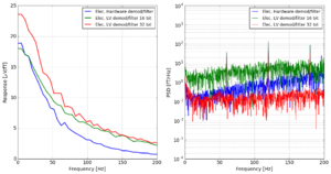
The 32-bit version performs as good as the hardware lock-in. For some reason, the hardware lock-in PSD noise increases for higher frequencies, and for the 32-bit FPGA lockin it doesn't. The 32-bit version has 50 times smaller noise level than the 16-bit version.
 NoiseCompare(day='2016.08.31', run='14', noise='02', bs=1, Chan=1, direc='Y', label='Elec, Hardware demod/filter',
 ver='v16', fmax=200, radresp=0, calib=2e-06, Ipr=0.0001, psn=0);
 NoiseCompare(day='2016.08.31', run='00', noise='02', bs=1, Chan=1, direc='Y', label='Elec, LV demod/filter 16 bit',
 ver='v16', fmax=200, radresp=0, calib=2e-06, Ipr=0.0001, psn=0);
 NoiseCompare(day='2016.09.16', run='32', noise='02', bs=1, Chan=1, direc='Y', label='Elec, LV demod/filter 32 bit',
 ver='v16', fmax=200, radresp=0, calib=2e-06, Ipr=0.0001, psn=0);
The data is acquired at the sampling rate of 500 ksps, and then averaged to approximately 200 sps (final FPGA filter has fc=180 Hz). This should improve the bit resolution by a factor of Sqrt(500 ksps/200 sps) = Sqrt(2500) = 50 (6-7 bits).
The estimated gain was 25 μV/fT. The LSB voltage step is 300 μV, the effective LSB after averaging should be 300/50 = 6 μV = 0.25 fT.
Filtering/digitization
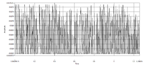
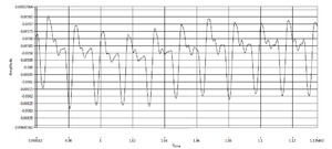
The digitization of the signal is not visible in the 32 bit version.
16 bit FPGA filtering
32 bit FPGA filtering
Issues with the 32-bit magnetometer
- [FIXED] 16-bit and 32-bit versions return substantially different (20-50%) magnetic field response to both Y and Z fields in Z-mode, although the sensor conditions are the same. 32-bit version reports increased gain for the Y signals, and decreased gain for the X signals
- The op-amp phase response rolls for 32-bit version for about 30 degrees in 0-200 Hz; the phase is flat in the 16-bit version. The phase behavior could be caused by a 0.5ms delay between the reference data and the input data.
- [FIXED] The op-amp response: phase at zero frequency is flipped by 180 degrees in 32 bit version
- [FIXED/not reproduced?] Calibration chirps are cropped too much in the beginning
- [FIXED in 32-bit version] Sometimes the subsequent calibration chirps come out at different DC levels. The magnetometer output looks like there is a sudden field jump between the chirps. Sometimes the jumps are larger than the magnetometer range. The jumps seem to be bigger when the field is not completely zeroed. Both 16-bit and 32-bit versions do that.
- [FIXED] Calibration chirps go too far out in the frequency domain and reach 1kHz, the modulation frequency. This causes the X field to not be demodulated incorrectly. Both 16-bit and 32-bit versions do that.
Other issues
- After replacing the fiber connector with the plastic one, the probe beam appear to become spontaneously imbalanced every few seconds. Most of the time it works fine, but sometimes it starts this weird behaviors. It's unclear if it's the connector, or the laser, or the electronics.
09/22/2016
Thursday group meeting.
Zack showed new custom-made non-magnetic fiber connectors. They are improved compared to the previous version, so that they can be cleaned without taking the fiber out and exposing the bare glass. It's important because that's how we broke our fiber the last time and had a downtime of over a week. We have a few dozens of them, and they are machined in the machine shop downstairs.
The field that we have in the magnetically shielded room drifts a lot. The full range of our device is approximately 0.5-1.0 nT (±10 V ADC input at 10-20 μV/fT) Thad proposed to use a 3-axis fluxgate to stabilize the field and keep it within the range.
Thad also proposed to increase amplitude of the calibration chirp at higher frequencies in order to have a better S/N for higher frequencies. I think it would be easier to increase the duration of the chirp at these frequencies, because the amplitude is already fairly close to the maximum.
09/23/2016
Chirp DC offset
Looking for the source of the bug where the magnetometer output jumps before outputting the calibration chirp. This results in the chirps not being at the same DC level, and sometimes going out of range.
We (I and Zach) are thinking that this might be because there is some random voltage on the Z-mode outputs while the chirps are running. I connected the FPGA outputs to the scope to see what they are outputting. I also recompiled the FPGA firmware to make all 4xint16 ↔ int64 converters compiled as pre-allocated clones, because I thought that maybe the pool of them wasn't large enough for the FPGA to function. (That didn't change anything.)
I don't see any DC offset on the Z-mode outputs. The chirps are always output without the DC offset, but sometimes after the VI finishes the chirp voltage is set to some DC level. It happens once in 2-3 runs, and the voltage is proportional to the amplitude of the chirp. I think it's because the "FPGA output zeroes" subVI is not doing that, and the DC level is a part of the next chirp.
Modified the "Send Chirps" subVI so that "chirp?" variable is only written once at the first call, that solved the problem.
Op-amp calibration phase roll
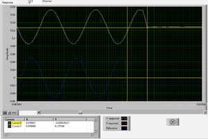
Added a graph to output the signals coming from the Host VI when the calibration is running. The response signals are delayed by 0.5 ms with respect to the reference signals. It's not caused by the circuit because the features are not low-pass filtered. The chirps end at different times.
Weird things happening
- Some DMA channels are backlogged by a different number of samples than others
- Actual DMA rate starts out at 100000, ends at 363636, but Chirp generation ticks stays at 110 @ 40 MHz at all times
09/27/2016
New magnetometer cells from Precision Glassblowing in DC mode
The new cells has finally arrived. Zack replaced cells 3 and 4, and took the noise measurements in DC mode.
Cells 3,4 are the same and T=120C, but 1 and 2 have different buffer pressure and temperatures. The lasers are tuned to find a "compromise" between the cells, so that all of them demonstrate a reasonable performance.
09/28/2016
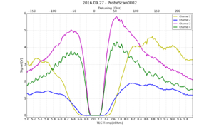
Magnetometer signal vs probe detuning
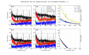
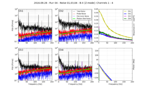
New magnetometer cells from Precision Glassblowing in Z mode
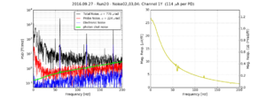
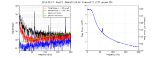
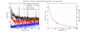
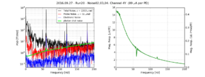
Same set of cells (1,2 are the old cells, 3,4 are the new cells) in the Z mode.
Y channel (DC response)
X channel (demodulated response)
09/29/2016
Group meeting.
There is a paper on ArXiv that reports a method to increase the sensitivity of a Faraday rotation experiment by over two orders of magnitude. If true, we could achieve spin-projection noise easily, and improve by a factor of 10-100 on our magnetometer sensitivity. https://arxiv.org/abs/1609.00431
Local copy as of today: File:1609.00431v1.pdf
The paper is very poorly written, so it's unclear what exactly happens there and if the method does what they claim. Seems like something relatively easy to try, especially for 100x sensitivity increase o_O.
Probe sensitivity degrades when misbalanced
We are getting the best probe sensitivity when the balanced polarimeter is perfectly balanced. Sometimes it becomes misbalanced, and the noise floor rises significantly within 0-100 Hz range (where the heartbeat signal is).
Say there is a balanced polarimeter that has two channels - and , where is the total (noisy) light power, and is the optical rotation angle
Then the difference and the sum of two channels are:
Which are both proportional to the total light power.
If we take the ratio of the two, the light power dependence cancels out:


![{\displaystyle P_{x}(t)=P(t)\left[\cos \varphi (t)-\sin \varphi (t)\right]}](https://en.wikipedia.org/api/rest_v1/media/math/render/svg/2221f1ccdffe5bc8a8db94081fcc2849584a20dd)
![{\displaystyle P_{y}(t)=P(t)\left[\cos \varphi (t)+\sin \varphi (t)\right]}](https://en.wikipedia.org/api/rest_v1/media/math/render/svg/930300906f4ccfb72dc7f6a2f7bbac1172167034)


