Lena/Aug 2016
August 2016
08/15/2016
NURI paper
Talked to Dima about the NURI magnetometer network paper. His comments:
- The device section describes a solution without a problem. Add to the introducion:
- need for the accurate timing
- need to correlate signals from the different sensors
- magnetometer has to be portable
Mx magnetometer sensitivity
Talked to Thad about a possibility to have a synchronously pumped scalar Mx magnetometer in the fMCG project. The advantages would be:
- not having to cancel the field
- no calibration
- no 1/f electronic noise
Disadvantages:
- spin-exchange relaxation
- no vector sensitivity
Calculations for an Mx magnetometer built with a paraffin-coated 1cm3 cell show that it should be possible to get around 3 fT/sqrtHz per 1cm of the probe length.
- Download the Mathematica notebook - File:ScalarMagnetometerParaffinCells.zip
Alkali vapor cells sources
Asked around to find who could make some paraffin-coated cells for us. Dima's sources:
- Misha Balabas ($500-$700 per cell)
- Antonie Weis (sells 20x20mm cells that they no longer use)
- Wenhao's group (can make cells or fill cells)
- Precision Glass Blowing (had poor T1)
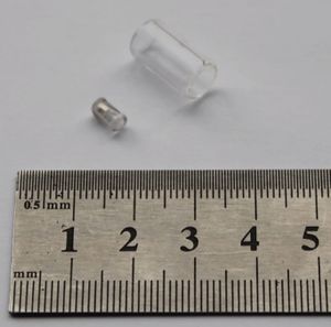
Asked Vitaliy Shutov from Frequency Standards Lab in FIAN, Troitsk. They have a setup that produces the cells in small (~10) batches. The cells are baked and sealed under vacuum and don't have stems. Cells can be filled with any gas mixture, but they don't make coating. The cells come in two sizes
- 8x15mm
- 5x3.5mm
Velichansky's group also has a stash of paraffin-coated 20x20mm cells.
They don't seem to have special documents (or knowledge of how to obtain them) for selling and shipping the cells. I figured it would be easier to buy from Precision Glassblowing than go through all that.
08/26/2016
Fundamental noise limit estimates
Finished the Mathematica models of the Mx in coated cell, SERF with buffer gas and SERF with OTS coating + 30 Torr Ne magnetometers. The models estimate the best achievable performance of each magnetometer in perfect circumstances (taking into account probe and pump de-pumping). Each magnetometer has a cubic cell of 1x1x1 cm. The magnetometers rank by sensitivity (from best to worst):
- SERF + OTS coating + 30 Torr N2 (0.1 fT/sqrtHz)
- SERF + 300 Torr N2 (0.5 fT/sqrtHz)
- Synchronously pumped magnetometer with a paraffin coated cell (1.5 fT/sqrtHz)
Mx magnetometers sensitivity is limited because they have lower alkali vapor concentration (can't heat coating above 60°C), and radiation trapping (no N2 in the cells). The SERF with OTS coating has narrower zero-field resonance line, so the probe can be detuned much closer than in the magnetometers with buffer gas. They also run at lower temperatures and so they have larger T1 due to decreased self-spin destruction collisions rate.
The fetal heartbeat largest feature size is of an order of 1 pT, so 1 fT/sqrtHz sensitivity seems to be still good enough.
Download here: File:Magnetometers fundamental limit 1cm3.zip
08/30/2016
The problem
The magnetometer can take the vector measurements in two channels: X and Y. The Y is orthogonal to both pump and probe, and provides the sensitivity to the main direction at DC, while the X direction signal is demodulated at 1kHz. An LabVIEW filter in FPGA is setup to separate the two signals. The Y signal is obtained by low-pass filtering the signal with two 2-order Butterworth filters, while the X signal is obtained by multiplying the time signal by a reference and low-pass filtering it by the same filters.
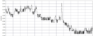
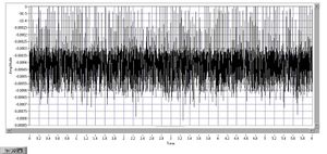
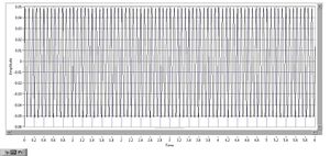
The problem is that the Y channel often has large digitization noise (see the picture). The digitization noise disappears when one of the Butterworth filters is deleted (but then the filtering is insufficient).
Investigating the filter response
We want to find how much the filtering affects the noise of the X and Y channels. To do that we take two measurements:
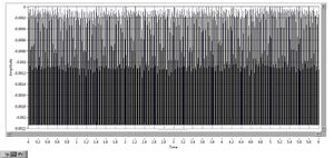
Technical noise
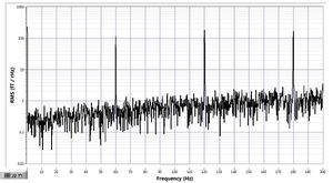
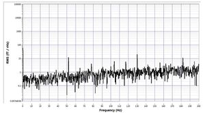
Zero volts from the frequency synthesizer is connected to the FPGA input. The data is stored in 2016.08.30, Run2, noise 6.
X noise (time domain)
X noise (frequency domain)
Y signal (time domain)
Y signal (frequency domain)
Known signal
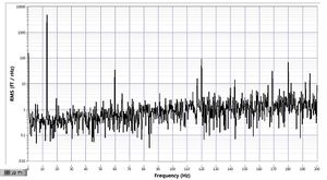
Mike suggested that we apply a known signal to the FPGA input to measure the noise produced by the processing VI. We are sending a 50 mV 13 Hz AC signal into the FPGA from a frequency synthesizer DS345. The data is stored in 2016.08.30, Run2, noise 7.
X noise (time domain)
X noise (frequency domain)
Y signal (time domain)
Y signal (frequency domain)
The strange thing
The PSD measurements with the 50 mV calibration signal seem to indicate that the technical noise is about of 1 fT/sqrtHz. But the largest response we can get from the magnetometer is 15 μV/fT. The ADC is 16 bit with ±10V inputs. So the resolution is 300 μV = 20 fT. How is this even possible?
08/31/2016
Issues with the data acquisition
I, Mike and Zak have discussed what might be wrong with the LabVIEW code. We have identified the following issues:
In the demodulation circuit diagram: two 16-bit integers are multiplied and produce a 32-bit integer, which is then scaled back to 16 bit. The original v16 program scales is by a factor of 2^-14, while it really should be 2^-16, to pick out the high word of the product.It should be 2^-15, and another factor of 2 seems to come from accounting for the demodulation with a sine, maybe because the integral of sin^2(x) is 1/2 ?- In the data sampling: the FPGA always acquires the data at 500ksps. The data is demodulated and filtered at 250ksps, and both these frequencies are hardwired. Sampling rate set by the host VI only sets the rate at which the data is send to the computer. This rate is smaller than the data acquisition rate, and the VI seems to discard the other samples, rather than average them.
- The ADC with the 16-bit resolution and ±10V input range is only sufficient to resolve ~10-20 fT at 15 μV/fT gain
- Filter cutoff for the low-pass filters is 250 Hz, which is very small compared to the fs = 500ksps, which results in the filter coefficients differ by 4 orders of magnitude, and the data is only 16 bits. Precision errors might happen.
- We are using Butterworth filter, which does not have a flat phase response. Having the flat phase response is very important to avoid distortions in the signal in the time domain. We should use Bessel filter instead.
LabVIEW biomedical signals processing library
Apparently LabVIEW has an entire library to process biomedical signals, including ECGs. Here is the link http://sine.ni.com/psp/app/doc/p/id/psp-1141/lang/en
