David Notebook
Things to Do/Check
- Shape 780 beam with prism pair
or send it through a fiber
- Why is 1064 current driver fluctuating?--switching it with 1555 fixes it. Should contact Vescent.
- Measure 780 power before and after cavity; see changes with cavity piezo
- Why is reflected 1064 signal fluctuating in power so much?
- What's wrong with the IR viewer?
Daily Log
8/26/14 Replaced the deuterium cylinder. It was taking a lot more from the old one to get to the same pressure than it used to (we usually fill a small tube between the cylinder and a secondary valve and put in multiples of that amount). Since it was taking more, the cylinder must have been lower pressure. We probably could have used the old one for a bit longer, but since the cavity hasn't been behaving well I thought it was worth switching now. Maybe something weird was going on, like the deuterium pressure was low enough that a significant amount of air or nitrogen was getting into the cavity through small leaks in the tubing.
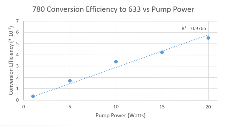
Still not getting nearly as high 633 generation as a couple weeks ago. I'm not sure why, but at this point we're just going to take data so we have something and maybe we can redo it later if things start working better.
| Pump Power (W) | Transmitted Pump Power (mW) | Transmitted Stokes (mW) | Generated 633 (nW) | Conversion Efficiency (*Failed to parse (Conversion error. Server ("https://en.wikipedia.org/api/rest_") reported: "Cannot get mml. TeX parse error: Prime causes double exponent: use braces to clarify"): {\displaystyle 10^{-7))|-|20||Example||Example||Example|||-|15||Example||Example||Example|||-|10||Example||Example||Example|||-|5||Example||Example||Example|||-|1||Example||Example||Example|||}'''8/25/14'''IdecidedtogowiththeMoglabswavemeter.We'llbemodulatingasignalfromapulsedlasersentthroughacrystaltofurtherbroadentheoutput.Zachhadpreviouslyworkedwiththisandhadsomespectrumdatafromit.Iwroteapythonprogramtocalculatethebroadenedspectrumwhichtook<math>10^{-6}}
of each spectral component and shifted it up and down by 89.6 THz. The resulting spectrum should have a few tens of nWs total average power in the 640-840 nm range, which is where we'd first like to examine since we can use the same optics we already have. Moglabs says they can build us a custom wavemeter with enough sensitivity so that it should be able to measure this whole range at a resolution of ~1nm. It won't be ready until November, but there's a fair amount of setup to do in the meantime. Upload data tomorrow
We're wrapping up the experiment using 780 as the independent mixing beam. Now that we have it working pretty well, we want to plot pump power vs 633 power at the optimal pressure I found, and measure the transmitted pump and stokes beams at each pump power. Josh and I have been trying to do this on 8/22 and today, but have been having some locking/alignment issues. Today the 1064 current driver was fluctuating more than usual and even the setpoint values for temperature and current limit were fluctuating. Something seems to be wrong and we need to contact Vescent. We switched to the 1555 driver, which fixed the fluctuations, although it did not seem to improve performance. We tried switching the slow locking circuit to control the cavity piezo rather than the laser piezo. Josh said they had previously had a better lock doing this, but we did found it to be worse and ultimately switched back. We eventually got the pump locking again, although poorly, and got some 633 generation, although low power. It's hard to say what's wrong. Some days it just doesn't work very well, so hopefully it will be better tomorrow. Ideally we'd want to take all the data in the same morning or afternoon to reduce random fluctuations. We want to make sure we're measuring 633 power and transmitted pump and stokes all at the same locking mode. It's hard to guarantee this unless we can measure them at the same time. We put in a flip mirror on the 780 side where the 1064 and 1555 reflect off the dichroic mirror. The beams then go to a prism and we will set up two power meters. So the plan is to get a good lock and measure 633, then quickly flip the mirror and record the 1064 and 1555 power values simultaneously.
8/13/14 The next step for the experiment will be to try to modulate a broadband signal. I'm looking if there's a cheapish wavemeter or spectrum analyzer option with high sensitivity, since we'd need to be able to look at a broad output rather than a narrow beam. HighFinesse--has some spectrum analyzers, but they don't seem sensitive enough. Moglabs--has a really cool looking very sensitive (pW) wavemeter, but it only has a bandwidth of about 20 nm when set at a given wavelength. It can measure over a wide range, but must be recalibrated. Maybe this could work though by slowly building up the spectrum? How wide an input are we thinking of? This wouldn't be practical if we'd need to search over hundreds of nm, but we could probably build up a small spectrum without much difficulty. Coherent--has a wavemeter, but too narrow bandwidth to be useful Thorlabs--has several spectrum analyzers, some of which are sensitive to nW, but only when doing long scans (~10s) which might be impractical. Also probably really expensive. Exfo--has a wavemeter but not sensitive enough Bristol Instruments--has a multi-wavelength meter, but not sensitive enough or over the right range. Yokogawa--has a very sensitive spectrum analyzer, but probably super expensive Optoplex--has both wavemeters and spectrum analyzers, but not sensitive enough
It was getting too hard to lock above 0.4 atm, and there were some difficulties at that pressure that might have accounted for the lower powers. As I increased the pressure, the difference in power between modes decreased and there were fewer modes with no 633 generation.
8/11/14 Using the regression equation from the data for the PDA36A, and accounting for the 16% higher power 633 nm light should have from the sensitivity differences, P=1.77V with power in nW and the lock-in set at 5 mV and the photodiode at 60 dB gain. I was getting chopped powers of about 2.3 nW today which is lower than what I calculated using the previous photodiodes. The 633 light seems noticeable brighter to me though. I'm not sure which is the best measurement--all the methods seem somewhat inconsistent. 633 generation is also much more mode dependent than previously--sometimes a lock will produce almost no 633. I think this is probably a result of being at lower pressure (0.1 atm). I'm going to try to stick to this photodiode for a while if I can. I'm still not sure if powers are converting correctly, but from my measurements yesterday it at least seems to be acting linearly and so I can compare measurements at different pressures and alignments. I should be able to easily normalize any measurements past this point if I discover the conversion factor isn't correct as long as the response is linear. I'm also going to keep the lock-in at the 5 mV scale, since the output doesn't always seem to scale exactly with the sensitivity as would be expected. I'll work at 0.1 atm for another half day tomorrow to make sure I can't improve the generation and then start increasing the pressure.
I tried a few other settings and 60 dB seems like a good balance.
Accounting for the new factors, chopped 633 power is now:
Well, the photodiode has a very non-linear response, both when looking at the output from the lock-in amplifier and with the chopper off and just looking on an oscilloscope. I checked this for powers in the mW range down to μWs, so I don't think it's just a saturation issue. The Thorlabs photodiode seems fairly linear. It seems the UDT photodiode has a logarithmic response at low powers. I can't find anything in the datasheets about this, but plotting about 10 points from 6 to 800 nW of input power vs voltage makes this fairly clear. I'm going to use a regression equation to infer powers from the voltage then. I'm likely in the 1-10 nW range, but the data is noisier here since it's hard to accurately measure down to nW with the power meter. I'm only going to use the data from 60-800 nW, which gives a good fit. Hopefully the response is similar at lower powers. Data is here I found the response curve to be Voltage Power with Power in nW for the output of the lock-in amplifier set at 50 mV sensitivity using the UDT photodiode and 780 nm light. I used 780 since it gives a much more stable output than the HeNe. Accounting for the sensitivity, the equation becomes Voltage*Sensitivity PowerThe photodiode is about 86% as sensitive at 633 as 780, so 633 powers should be 16% higher. Then for 633 light, we should have Voltage Voltage*Sensitivity Power
with power in nW. This is the chopped power at 400 Hz for 633 nm light. Hmm, this won't work for low powers though, since it's minimum value is the in 30s. I'll need to figure out a better way to do this, but it's difficult because I can't easily directly measure nW level powers to send to the photodiode.
I measured the transmission of the prism directly using the 1064 and 1555 diodes. I found 100% for 1064 and 89% for 1555. After the prism, I measured 20 mW of 1555 and 7 mW of 1064. I didn't use the bandpass filter since I would need to use the prism for the 1064 measurement anyway. Accounting for the prism, that gives 22.5 mW of 1555 and 7 mw of 1064 and 592 W and 219 W just inside the cavity. With the cavity mirror transmittances and beam sizes from yesterday, that gives cavity intensities of: and
8/5/14
Deniz can calculate the maximum theoretical conversion efficiency of 780 if we know the amount of 1064 and 1555 in the cavity. The cavity mirror transmits 32 ppm and 38 ppm of 1064 and 1555 respectively, so that puts the powers at 559 W and 1316 W inside the cavity. The beam sizes were both about 1700 μm 30 cm from the cavity,
I'm skeptical of the prism transmission figure, since I haven't observed losses like that. I'll check directly tomorrow when the cavity is aligned. The bandpass filter lets through ~65% 1555 and blocks almost all 1064.
8/4/14 The 780 beam seems to become consistently misaligned such that the power reaching the cavity drops by about 40% after a day or two. Maybe just using a higher power diode and losing the TA/fiber would work better in the long run, but for now here's the procedure that generally gets good 633 generation.
The power of the 780 reaching the cavity must first be maximized. Use the magnetic mirror on the 780 side of the cavity to send the beam towards the middle of the table and measure the power. This is the only place where the power meter can be easily put in. Adjust the alignment of the seed laser to the TA to maximize the power measured at the cavity--usually just one mirror is sufficient, and the horizontal adjustment tends to have a much larger affect than the vertical. Then re-walk to the isolator, and then finally to the fiber. These adjustments have a small enough effect on the overall position of the beam that it is not necessary to adjust the placement of the power meter. Repeating these alignments once more usually gives an additional 5% or so in power since the aligning to the TA and isolator will slightly affect the coupling to the fiber. Assuming that these adjustments have been small and that the 780 is still mostly aligned to the cavity, center two irises on the 1064 side of the cavity on the 780 beam with the irises placed a foot or two apart. Then maximize the HeNe power through these irises (close them all the way and walk it to get maximum power after the second iris) to ensure that it is overlapped with the 780 beam. This is usually a small enough adjustment that the HeNe is still centered on the photodiode, but occasionally re-centering it or even re-aligning it to the PVC pipe is necessary. Then align the 1064 beam as usual (cool the cavity, perform threshold tests, walk beam to get good free-spectral ranges). 633 should be visible in the flip mirror past the grating now when ramping the cavity. A signal may be detectable with the lock-in/photodiode at this point when locking the 1064, but note that it's possible that the 633 can be visible in the mirror and be aligned to the photodiode and still produce no signal on the Thorlabs PDA10A detector. This photodiode is better for getting an absolute power measurement of the 633 since it has a faster response time and produces good square waves, but the UDT Sensors PIN 5DP is less noisy and can be used at higher gain settings. The power of the 633 can easily vary by a factor of 10 with little change in perceived brightness in the mirror, so rather than try to re-align to the grating/PVC pipe/photodiode at this point, it's better to first switch out the photodiode, quickly recenter it using the HeNe (adjusting the photodiode position, not the HeNe alignment), and then maximize whatever signal is found by walking the 780. The alignment change by walking the 780 is small enough that it should still be overlapped well with the HeNe, but if the 780 alignment was very off it might be necessary to use the irises to overlap the HeNe again and check that it is still centered on the photodiode.
New efficiency measurement is In addition to walking the 780 beam, I also slightly adjusted its polarization and the focus of the a-sphere on the output fiber launch, both of which slightly improved efficiency.
7/29/14 I tried a variety of lens combinations again for a telescope, and adjusted the lens positions over a large fraction of the focal distance of the second lens, but they all failed to collimate the beam at the wall (~20 feet) better than just the a-sphere by itself. I've decided to go with just a single lens for now and if this doesn't improve the 633 generation efficiency enough, I'll maybe switch to checking other variables like gas pressure. Calculating the proper focal length for the lens doesn't seem practical since there is about 34 cm of propagation distance before the lens (a distance over which the beam diverges a non-negligible amount) and then 20 cm after the lens before the beam enters the cavity. Finally the cavity mirror will also adjust the focus somewhat. I modeled this setup with a spare cavity mirror and just tried different lenses to see what works best. A focal length of 400mm was a good compromise, giving a beam size of around 930 at the start of the cavity, 630 in the middle, and 1075 at the end. While the 1064 is 810, this is actually only at the center and is somewhat larger at the front and back of the cavity--these sizes for the 780 beam might be alright then.
7/28/14 Further measurements on Friday showed that the beam actually still diverged quite a bit after the telescope, to the point where it won't be useful. The performance seems limited by the laser/a-sphere which will not fully collimate out of the fiber. I'm switching out the 110 a-sphere on the output for a 230. It doesn't collimate quite as well, but with a shorter focal length, I'm hoping it will be smaller over a propagation distance of about 1 meter.
7/24/14 The camera was extremely temperamental. The XP computer in the other lab room would recognize it and work, but the laptop would not. I re-installed the software/drivers, which didn't fix it right away, but eventually I got it working. I couldn't say what I did. The upper USB port on the right side of the laptop worked for it though--some of them seem to give better luck than others. With the TA all the way up, the beam is way too strong for the camera to properly image, but I don't want to turn down the power in case it affects the beam size. I put in a 780 notch filter, which always it to be imaged without overloading at the shortest shutter speed and low sensitivity. I don't think the notch filter should affect the shape much, especially since the beam has already been filtered by the fiber and should be almost all at 780 nm. I turned the chopper off since it runs at a similar frequency to some of the shutter speed options and was interfering. The beam looks very Gaussian as expected. Measurements are as follows, with sizes using the "13.5%" ( value:
The beam is in the cavity and should be overlapped with the 1064 from about 22.5 cm to 97.5 cm. The 1064 beam is about 810 by 810 μm, so the beam is too big in some areas. Following Jared's advice, I made a telescope with a 150 mm lens and a 75mm. By putting the 75mm one 225 mm from the 150 (f1+f2), the final beam should be fairly well columnated and smaller. This easily reduced the beam from around 1200 to 850 μm, which was very promising. I'll test more precise alignments and different lens combinations tomorrow. I'll have to rearrange the 780 optics again to accommodate a setup like this, but ti seems worth it if I can produce a sub 810 μm beam through the whole cavity.
7/18/14 The value that the lock-in displays is actually slightly different from what it outputs. When viewing the signal on an oscilloscope, the mean voltage better matches what I would have expected yesterday (about 8.6 V for a 2 V peak to peak square wave--closer to the 9.0 V it should be than what the screen shows). Looking at the output of the function generator on another oscilloscope revealed that the output is slightly noisy--this might account for the difference in the expected and measured values. I'm going to just assume that the lock-in is operating on square waves according to the formula from yesterday. It's certainly close. The photodiode is definitely too slow for the chopper. The rise time is plenty fast, but it seems there is a fairly long decay time--the waves were asymmetric, with the first half looking good and the second half looking like an exponential decay. They got worse with increasing chopper frequency. I switched to a Thorlabs PDA10A, which has no problem even at 1000 Hz. At 633 nm, it has a listed responsivity of about .38 A/W.
With the .38 Amps/W as the responsivity of the photodiode and the V/Amps is the transimpedance gain of the photodiode. The results agree! This is the power with the chopper on, so double it if we want the actual power that could reach the photodiode.
I measured the power of the generated 633 beam using this technique and found a typical unchopped value to be 5 nW. About the same value as before, but I'm much more confident in the calculation technique. This gives an efficiency on the order of , so the next steps should probably be better shaping the 780 beam since there don't seem to be many gains left to be made in alignment.
Jared and I have both thought that the visible power meter head has been giving somewhat high values (10% or so), so I'm skeptical of its readings. However, further investigation of the lock-in reveals the display signal is always multiplied by an additional factor of 10, regardless of the gain settings. Page 21 of the manual alludes to this, but I couldn't find a full description. I measured this value as closer to 9 though--I used a function generator to send in a square wave at 500 Hz with a max amplitude of 2V and a min of 0V, similar to the type of signal the photodiode should send in. With the gain setting on the lock-in as "1 V" or "1 μA", the output was 9 V. A 100 mV average value square wave gave 0.9 V. Ok, the multiplicative factor of 9 is checking out more--it matters for the lock-in whether the input signal is a sine wave or square wave. For a sine wave, it singles out anything oscillating at the set frequency and gives the RMS voltage. For a square wave, it takes only the first Fourier component (2/π sin(ωt)) and then the RMS value (multiplied by ). Page 31 in the manual is helpful. So for a square wave pulsed laser at 500 Hz like I'm sending in, the output voltage should be
I also noticed that I am not getting perfect square waves from the laser/chopper/photodiode combo. While it works well at low frequencies around 40 Hz, at 500 Hz where I was running it the waves are distorted. This is likely because the response time of the photodiode is not fast enough. This should not affect optimization procedures, but it does mean that the Fourier component at 500 Hz does not have an amplitude factor of 4/π. I will either need to run the chopper slower if there is not too much noise at lower frequencies, or calculate a better value for the pre-factor before converting to an absolute power value for the 633 beam.
From page 69 in Josh's lab book #1, the 780 notch filter transmits about 19% at 633. This seemed low and I measured it with the HeNe as 88%. It seems like the curve for the notch filter is incorrect and I probably should recheck the cavity window and mirror curves with the spectrophotometer at some point. For now, I'm just going to manually measure everything with the HeNe and 780 TA.
Notch Filter: 88% Cavity Mirror (spare): 77% Cavity Window (spare): 79% Both: 61% Or 65% for the pair when measuring through the actual cavity (took the square root since the generated 633 will only pass through one pair). I'll use this value. 29% through entire path past cavity (pickoff is first element; grating is last element; 633 bandpass filter is in) or 22% with a 780 notch filter in. The power for the 633 fluctuates somewhat, so these are not super accurate. The chopper cut the measured powers almost exactly in half as expected. So with the 633 bandpass filter and the 780 notch filter, .61*.22 = 13% 633 gets to the detector, or 6.5% with the chopper on.
Our current efficiency then is 21 nW/156 mW = (use chopper-on value for 633 since we use the chopper-on value for 780).
7/15/14 Further 780 alignment optimizations have raised the 633 power at the photodiode to 1.9 nW (3.8 accounting for beam chopper). I put in a 780 notch filter right before the photodiode to make adjusting the 780 alignment easier--the scattered 780 at the photodiode changes when adjusting its alignment, which washes out a change in the 633 signal. Hopefully this will make changes in 633 easier to detect.
11:43 am I see something! I'm almost positive. Is champagne allowed in lab? What time does happy hour start at the library? When locking the 1064 beam with the 780 on, there is a noticeable jump in signal that is not present with the 780 off. Turning on/off the 780 changes the DC offset of the signal, but the jump when locking is about 10 times higher when 780 is on. The signal is clearly correlated with the lock. Settings are as follows: Gas Pressure: 2.515 volts 633 bandpass filter is in place before the diffraction grating Oscilloscope scale is 20 mV (signal when locking jumps ~100 mV) Chopper frequency: 500 Hz (chopper is outputing the frequency to the lock in--one of several variations I've tried including using the lock-in to set the chopper frequency and using a function generator to set both frequencies. Having the chopper in charge seems to be the most stable). Lock-In: signal input (using only built in amplifier)-- I (), time constant-- 1 sec, slope/oct-- 12 dB, sensitivity-- 50 μV, reserve-- low noise, filters-- off
Checked the power output on the TA and found it was only about 300 mW. Re-aligned the seed laser and the power is back to 1 W. This increased the locking signal, which comes to about 60 pW as measured the detector. Since the chopper is blocking the beam 50% of the time though, the effective power is 120 pW. There are other significant losses from optical elements as well--about 40% of the incident light on the grating goes into the first order at 633 nm (as measured with the HeNe), 93% for the 633 bandpass filter (measured with HeNe), 60% and 70% for the cavity window and mirror, 90% for the dichroic, and 3 silver mirrors and the cavity pickoff at 95% each. All together, this means that we are only getting 5.7% power at the photodiode, including the 50% reduction from the chopper. So inside the cavity there should be about 1 nW of 633. I turned down the current to the TA, reducing it's power by a factor of 3. This reduced the measured locking signal by a factor of 5, which is not linear but at least the measured power correlates with the 780. We're very convinced the signal is 633. After briefly playing with the 780 alignment, Josh and I increased the measured signal to .5 nW. There are likely many more gains that can be made. Suddenly we lost the signal in the afternoon for no clear reason. Eventually after realigning the HeNe and photodiode I was able to find it again, but it was back to the lower level of around 60 pW. Apparently the setup is very sensitive to a variety of factors, but this it to be expected if the signal is indeed from 633 generation.
Things to try this afternoon--remove photodiode and make sure 633 flashing is visible with current alignment, remove 633 filter--offset should change, but locking signal shouldn't change much (check how much 633 it should pass), move 633 filter to the front of the detector--does this reduce DC offset when turning 780 on/off?, turn down 780 power--does locking signal decrease linearly?
7/11/14 Spent the last 2 days setting up the beam chopper and a lock-in amplifier for it. It works very well and after sending the HeNe through 2 irises I could easily measure it 1 nW. I thought I was seeing a signal at one point that only appeared when locking when the 780 was one, but I haven't been able to replicate it yet. It's difficult to optimize the settings on the amplifier since I can only lock the 1064 for a second or two at a time. Is there some way I can do it while ramping instead?
7/9/14 Testing the 633 filter showed it lets through about 90% of 1555. We want to determine that most of the scattered light is 1555 like we think. So far we know the signal appears only when locking 1064 and that the cavity window cuts the signal by a factor of 5. It also seems to be only scattered light because blocking the path from the grating does not affect the signal. Evacuated the cavity and re-aligned 1064. Couldn't see what we've believed to be the 633 beam (as expected) although I couldn't figure out how to re-overlap the 1064 and the 780 beams (usually we use the generated 807 beam, which passes through the dichroic mirror). Hopefully I'll be more clever tomorrow. The 1064 alignment was only marginally more than for a typical morning though, so I don't think it would be moved so much that the 780 wouldn't overlap enough to generate 633 if gas were in the cavity. I found that the signal to the photodiode when locking was actually much higher now--about 20 nW. This happens whether 780 is on or off, so it can only be from 1064. This may suggest it is not 1555 as we suspected, although there is much more 1064 generated when locking with no gas in the cavity (I measured about 200 mW exiting the cavity when locking today), and 1555 might still dominate when there is gas. Putting the cavity mirror in front of the PVC pipe drops the signal by a factor of 50 to .4 nW (was I off by a factor of 10 when I checked with gas in the cavity? I don't think so, but maybe recheck). Since the signals when locking don't seem to be from 633, the .4 amps/watt value I've been using for the photodiode to calculate powers is probably incorrect. For 1064, it is closer to .25 (so powers are actually higher), and it is unrated at 1555. Still, the relative power drops are useful. Removing the cavity mirror and completely blocking the PVC opening with a book still let through about .25 nW, so actually when the cavity mirror is in place about as much light gets to the photodiode from the PVC pipe as from through the cloth. Maybe it's time to make a better case for the photodiode. Still, since the book cuts down the signal by a factor of 80, most of the light does enter through the PVC pipe opening. Does the cloth transmit significantly more of either 1064 or 1555? So at least some of the locking signal is from 1064, and some is likely to be 1555 as well. The cavity mirror helps and other filters probably would as well, but it still seems the best option is to use the beam chopper.
7/4/14 It still seems that there is no difference in signal whether the 780 is blocked or unblocked, and there is a clear signal of around .5 nW when locking the 1064. The HeNe is not staying very well aligned--I hoped only a horizontal adjustment would be necessary, but it seems unscrewing it from the pedestal creates too much of a vertical change.
7/3/14 Had some difficulty with the 1064 beam today, see 1064 laser notes. I also realized that even after getting the HeNe laser going through the cavity and hitting the diffraction grating, there was still a fair amount of play with the mirror walks which ultimately could move the beam at the photodiode by a couple inches. The generated 633 beam might be missing the detector then. I put two irises in the 780 beam path after the cavity and separated by a couple feet of path length. After lining up the iris to the 780 beam, I swapped in the HeNe and used its mirror walk (which is independent of the 780 path) to align through both irises and then put the photodiode and lens in this beam path. Hopefully the generated 633 beam will be overlapped with the HeNe path now and is hitting the photodiode. Maybe try using a very large diameter lens before the photodiode so there's more tolerance?
7/2/14 Decided to try propagating the beams across the lab instead of making a PVC maze in hopes of getting good spacial separation. We borrowed a breadboard from the optics lab and aligned the HeNe through a PVC pipe about 15 feet away from the diffraction grating. The beam then goes through a lens and onto the photodiode mounted on a translation stage. There is still a signal when locking the 1064 beam, even with the 780 blocked. The signal does not change unblocking the 780 when the 1064 is not locked, so there is no 780 beam getting to the detector. Whatever it is seems to be from the 1064 or a sideband as we previously believed.
7/1/14 Realigned 1064 to the cavity and 780 beam after they had been left alone for a few weeks, and got 633 visible again by eye through the flip mirror. Re-overlaped the HeNe beam with the 780 path so that I can see where the generated 633 beam should go. USA is out of the world cup.
Business School/Vacation
6/13/14 We set up a diffraction grating over the past two days (G=1800; reflective in visible light region; borrowed from Saffman group), which gives better angular separation between wavelengths than the prism. Using the grating equation,
(page 22 in Newport Diffraction Grating Handbook), 780nm and 633nm should be separated by about 18.6°. We overlapped a HeNe (λ=632.8 nm) with the 780 laser path, and then used this to figure out where the generated 633 should be. We set up a 1 inch flip mirror for viewing by eye and had the photodiode behind it. This worked very well and we were immediately able to see the 633 in the mirror, which was aided by the fact that it was much smaller than the 4 inch mirror we used before and we could set up the irises using the bright HeNe signal. We could still not see a definitive signal for 633 with the photodiode though, although we are confident we are hitting it or are extremely close. We mounted the photodiode on a translation stage, which we will try adjusting next.
6/11/14 We aligned once more with the camera today, and also noticed that the waveplate after the 780 TA was not set optimally to match the polarization of 1064, which would reduce 633 generation efficiency. Fixing this and getting a better alignment of the 1064 beam with the cavity today let us see 633 through the prism again, with about the same level of brightness as previously. We could still not see it through the fiber, but this is likely just a coupling problem so we aren't concerned. We looked at the signal from the photodiode after the prism, and also a pickoff from the 780 TA and found them both to be very correlated with the cavity piezo movement. The 780 seed laser still seems stable though. We also found some correlation with the prism photodiode with only the 1064 beam on, so 1064 or a sideband must also be getting through to the photodiode.
6/9/14 We realized just before DAMOP that we were getting feedback to the 780 laser. A lot of it seems to be coming from the cavity mirror, since the frequency/mode of the 780 seed changes when adjusting the cavity piezo. After retuning the isolators, the seed laser appears stable both on the OSA and wavemeter when adjusting the cavity piezo. We noticed there is still some change in signal on the photodiode when adjusting the piezo, and this occurs even with the 1064 off, so it seems there are still small back reflections affecting the 780. This is a much smaller effect than previously though, and since it isn't causing the laser to jump frequencies, we think it shouldn't be a problem.
Poster (PDF PowerPoint)
5/20/14 We continued to try to measure the 633 beam using the OSA and a power meter. We still couldn't detect anything, and the power meter measurements put an upperbound on the power in the nW range. The 780 seed laser hadn't been staying single mode very well, which could be reducing 633 generation or spreading it out to nearby wavelengths. We decided to try to fix this before continuing the search for 633. We tracked the 780 problem down to ASE feedback from the TA getting through the isolator and to the seed laser. This was eventually solved (see 780 laser notes). We're hoping this will increase 633 generation, and the nW power upperbound might no longer be accurate. We will look using the OSA and power meter again tomorrow and also using a photo-diode with high gain, which might be more sensitive. We swapped the ________ photodiode and unplugged the 1555 reflected signal, which we will try to remember in a couple weeks when it doesn't work.
5/14/14 1064 laser was more difficult than usual to align, was very prone to drift, and only locked passably well. Gas pressure is about 0.3 atm. Josh says it's been like this for a few days, although it seemed to show slight improvement in the afternoon. We set up a mirror on the 1064 side so that we can send 807 from the cavity to a fiber launch or a prism. Despite having the dichroic as one of the coupling mirror to the cavity, on the Saffman group's OSA, we could see all 3 beams with rotational sidebands (should only by 807, but 1064 and 1555 were about the same power as 807 instead of much stronger). It seemed there were some only vibrational modes too, but we haven't tried to repeat this yet.
780 Laser NotesTapered Amplifier (TA) is a 3 micron chip 1W 780 nm from Eagleyard Photonics. TPA-0780-01000-3006 Specified maximum rating is 3 amps of input current when seeded, but should be able to output 1W with 2 amps. There should be about 2 mW of power going into the TA, although 5-10 mW should be fine if the output power still isn't at 1W with the current around 2 amps.
1064 Laser NotesThreshold tests Usually get around 100 μW at 20 mA of current. A small adjustment of the diffraction grating (~a quarter turn total) will usually show little adjustment in output power, except for a narrow spike and drop off near the optimal grating feedback setting.
Long-Term Ideas
|
|---|


