Lena/Oct 2016: Difference between revisions
ElenaZhivun (talk | contribs) |
|||
| (8 intermediate revisions by one other user not shown) | |||
| Line 175: | Line 175: | ||
Expected attenuation with fc=20kHz (shielding + input filter + output filter) is 14 + 3 * (6 + 12) = 68 dB |
Expected attenuation with fc=20kHz (shielding + input filter + output filter) is 14 + 3 * (6 + 12) = 68 dB |
||
Expected attenuation with fc=10kHz (shielding + input filter + output filter) is 14 + 4 * (6 + 12) = 86 dB |
Expected attenuation with fc=10kHz (shielding + input filter + output filter) is 14 + 4 * (6 + 12) = 86 dB |
||
This noise will alias when the ADC samples at 20kHz, with a peak at 10 kHz, the digital low-pass filter should be able to take care of that. |
|||
Low-frequency gain of the differential polarimeter seems to be larger than the of SR570. It's unclear if it's a feature or a bug or a poor connection. |
Low-frequency gain of the differential polarimeter seems to be larger than the of SR570. It's unclear if it's a feature or a bug or a poor connection. |
||
== 10/24/2016 == |
|||
=== Testing the difference/sum mode === |
|||
Tested how the difference only mode compares to the difference/sum mode in terms of field sensitivity. Both measurements were taken with the same polarimeter board. |
|||
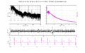
When the polarimeter is balanced, the probe sensitivity in both modes is the same. When the polarimeter is misaligned, the noise in 0-10 Hz band increases for the difference-only polarimeter, but not for the difference/sum polarimeter. In overall, the noise floor for difference/sum polarimeter is really good and the probe noise level drops rapidly in 0-0.5 Hz band. |
|||
=== Small polarimeter imbalance === |
|||
Difference between channels' light powers is 1.4 μW. |
|||
[[File:20161024SmallImbalance.png|300px]] |
|||
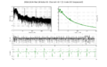
=== Large polarimeter imbalance === |
|||
Difference between channels' light powers is 6 μW. |
|||
[[File:20161024LargeImbalance.png|300px]] |
|||
== 10/26/2016 == |
|||
=== Pregnant patient in WIMR === |
|||
Measured a pregnant patient in WIMR. Although all channels worked properly and probe sensitivity was 1 fT/sqrt(Hz), we didn't get any good data, and couldn't see the fMCG signal at all. Maybe there were large field gradients that we didn't properly get rid of, like from wires in a bra or other clothes. The patient returns on November, 14th. |
|||
Added a real-time fMCG preview into the FPGA so that we don't end up in this situation again. |
|||
== 10/27/2016 == |
|||
=== Pulse-density modulation === |
|||
Implemented delta-sigma PDM (pulse-density modulation) for the FPGA. Now the FPGA can output "analog" control signals from the digital outputs, which our FPGA has plenty of. This would allow us to control every sensor shell coil on all three axis, and permit us to feedback on the field to keep all the sensors in average zero field and thus extend the dynamic range of our measurements. The signal to noise ratio in 0-1 kHz range is surprisingly good, and is around 100 dB. The VI is configured to output the "analog" levels with 16 bit precision. The switching rate is 20 MHz, with the CLK output. |
|||
We want to drive the atoms with the high-frequency signal and have them act as the low-pass filter. Mike built a current supply for the coils that reverses the polarity of the coil current for 0 and 1 logical levels. |
|||
It would be great to replace the analog inputs with digital signals as well. This would permit us to use a bigger FPGA (NI PXIe-7971R) that could drive as many as 25 sensors. Texas Instruments has Verified Designs section, that explains how to design and layout ADC circuits. [[File:TI ADC design ECG.pdf]] |
|||
=== Group meeting === |
|||
Thad is concerned that the excessive noise in our measurement could have been caused by the probe power noise. We need to modulate the pump power and see how in affects the measured field. |
|||
== BACK/NEXT == |
|||
[[Lena/Sep 2016|<< BACK]] [[Lena/Nov 2016|NEXT >>]] |
|||
Latest revision as of 21:32, 2 November 2016
October 2016
BACK/NEXT
10/03/2016
fMCG setup TODO
- Feedback system to keep the fields from "running away". Only the main XYZ fields need to be stabilized, the gradients don't change much day to day
- Reduce the polarimeter noise when misbalanced
Eliminating polarimeter noise when misbalanced
The existing current amplifier consists of two photodiodes connected in a way to add or subtract their photocurrents. The output of this passive circuit is connected to an SR570 current preamplifier.

I want to replace this circuit with something that can output both sum and difference, so that the common mode variations can be cancelled. Apparently a circuit that is supposed to do that has already been designed (see the link). The circuit has very little documentation and needs to be modified to increase the gain. We need 1-2 μA/V on the differential channel and 100-200 μA/V on the sum channel.
10/06/2016
New photodetector
Started on the new photodetector design and prototype here.
Lab meeting
Quick division
FPGA has hard times dividing numbers. Matt mentioned that there is an algorithm that quickly inverts any int32 number by multiplying it with a "magic number". https://en.wikipedia.org/wiki/Fast_inverse_square_root Never mind, it's for the floating point numbers.
fMCG setup field stabilization
Zack and Mike tried to stabilize the field in the magnetically shielded room by controlling the room coils with a feedback look (Y direction only). They tried the fluxgate, but it's sensitivity is not enough, as the polarization rotation signal is going offscreen. The stabilization system works well when the magnetometer signal on the Y channel is used for the feedback control. The bandwidth of the feedback is DC-0.5 Hz. The only problem is that when the sensor is tilted it doesn't work as well.
Shot noise limit for 10 USD
Thad mentioned there is an article by Hobbs titled "Reaching the shot noise limit for $10". File:Shotnoise opn.pdf
Downsample the magnetometer signal to 1 kHz
Zach mentioned that all the existing post-processing software expects the data to be sampled at 1 kHz. Right now it's at 20 kHz, and it's causing problems.
10/10/2016
Zach made an adult measurement with all four channels running. The large signal towards the end is Zack adjusting the field.
DC run 1
Channel 1
Channel 2
Channel 3
Channel 4


DC run 2
Channel 1
Channel 2
Channel 3
Channel 4


Z mode run 1
Channel 1Y
Channel 1X
Channel 2Y
Channel 2X
Channel 3Y
Channel 3X
Channel 4Y

Channel 4X


Z mode run 2
Channel 1Y
Channel 1X
Channel 2Y
Channel 2X
Channel 3Y
Channel 3X
Channel 4Y

Channel 4X


10/12/2016
Discrepancy between the expected and measured DAQ noise
It seems like the noise we are measuring is somewhat lower than what our bit depth suggests. With 16 bit ADC and downsampling from 500 ksps to 180 sps, we should have effective 21.8 bit resolution. The DAC range is ±10V and the magnetometer gain is 26 μV/fT, so the resolution should be 0.2 fT at DC. The noise on the PSD goes below 0.1 fT:

Talked to Mike, he says it's because of the difference between the resolution and standard deviation of of that signal. If the noise is gaussian, it should be a factor of Sqrt(12)
Ripples
There are some ripples on the magnetometers calibration. They might be caused by the windowing.
Adding an anti-aliasing filter to the polarimeter
In order to run the data acquisition at a smaller rate, we can place a hardware anti-aliasing filter on the differential polarimeter boards. This would take the computational load off the digital system and relax the requirements on how fast we acquire the data. Mike suggests replacing adding an active two-pole filter at the output of the polarimeter board. We can place a quad OP140 on the board instead of the dual version. The filter design is described in Horowitz and Hill in CH5.07 page 274. We would need to try different filters to see which one works best for our signal.
Expanding the number of channels
I checked the National Instruments website to see what equipment we might need to expand the number of channels. Each channel requires two analog inputs (Differential and sum polarimeter signals) and two analog outputs (chirp/calibration signal and Z-modulation). We could save one AI by only recording the difference signal, or add one AO if we want to modulate the field along two axes and get three-axial output. We potentially want a digital feedback on X, Y fields as well.
There are several main approaches we can use. The first approach is to have multiple FPGAs, each one controlling a set of four magnetometers. The cheapest NI FPGA (7851R) costs $2.8k, equating is $700/channel. The drawback is that the FPGA only has 8 analog inputs and 8 analog outputs, and there are no analog outputs free for the feedback signals. There are still free digital outputs that the FPGA can use to talk to an Arduino over SPI or something similar. Using FPGAs will result in the fastest feedback with proper timing. We don't have the requirements for the feedback to be fast (its band is DC-0.5 Hz as of now) With the signal normalization the FPGA is already close to its limit of slices.
The second approach is to use a PXI rack with stacks of ADCs and DAQs. The advantage is that we can add DAQs very easily by adding new boards. We could use a dedicated real-time controller to process the data, and if both DAQs and ADCs support NI DAQmx then the real time controller is not really needed. These boards have their own controllers that ensures timing, and the data processing can be done on the host computer. Each sensor running at 20 kHz with 18-32 bit resolution should produce around 1 MBit/second of data, which is very manageable. With a dedicated controller the price would be $500/channel, and if the host does the data processing it's $230/channel. If a general-purpose is a computer, then the feedback would be limited at 0-10 Hz. If a dedicated real-time controller is used, 100 Hz should be easily feasible, but 1 kHz and above might be tricky. To say for sure, I would need to look further of whether you can continuously acquire the data with DAQmx while sending it to the controller.
The third approach would be to use a dedicated microcontroller for each channel. The downside of this approach is that it would take the most of the development time, although the parts would be the cheapest. The microcontroller would need to be chosen very carefully, as many of them don't have enough processing power to process the data (many are 8 bit and don't have a multiplier). Microcontrollers don't typically have high-resolution DACs and ADCs built-in. These would need to either come on a development board and connect to each other, or laid out on a separate board with the microcontroller. Task scheduling would need to be coded by hand, too.
Relevant NI devices
Shot noise is ~1 fT/Sqrt(Hz)
| Type | Model | Channels | Bits | Speed | Expected noise (10 μV/fT gain) fT/sqrt(Hz) | Price USD |
|---|---|---|---|---|---|---|
| FPGA | PXI-7851R | 8 AI, 8 AO | 16 | 500 ksps each | 0.58/Sqrt(12) = 0.16 | 2800 |
| ADC | PXIe-6358 | 16 AI, 4 AO | 16 | 1250 ksps each | 0.28/Sqrt(12) = 0.08 | 5532 |
| ADC | PXI-6281 | 16 AI, 4 AO | 18 | 500 ksps scanning | 0.58/Sqrt(12) = 0.16 | 1929 |
| ADC | PXI-6289 | 32 AI, 4 AO | 18 | 500 ksps scanning | 0.82/Sqrt(12) = 0.23 | 2244 |
| DAC | PXIe-6738 | 32 AO | 16 | 350 ksps each? | -- | 1530 |
| Controller | PXIe-8840 | - | - | - | -- | 4500 |
10/13/2016
Talked to Chad and Jesra Tikalsky about the controllers for driving the sensors. Basically, if we can find an evaluation board with ADCs that's the way to go. If we design the board ourselves it will likely end up being a pain, and we would want to have an EE engineer to do that. We'll end up with a precision ADC and a noisy MCU at the same board, which is tricky.
Other than the evaluation board or an engineer, we could try the Raspberry PI with external DAQs. We could either run the stock kernel and do chrt, or write a kernel-level application, or find a real-time system for it, or run our application without the OS, but then we would need the basic drivers.
Jes also mentioned that 8 AI, 8 AO is a very small FPGA, so maybe there are FPGAs that can drive all sensors at once.
We can make DACs out of the digital FPGA pins with PWM http://www.allaboutcircuits.com/technical-articles/turn-your-pwm-into-a-dac/
10/20/2016
Testing the new differential polarimeter
inally completely debugged the differential polarimeter v0.1. Prototyping in the electronics shop turned out to be a bad decision because of the low board quality. Through-hole pads kept falling off, and most of the vias were busted.
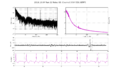
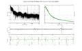
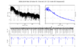
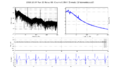
The device itself performs as good as the SRS current preamplifier. We took several magnetic field measurements with both current amplifiers:
SR570

Differential polarimeter v0.1

Design problems
There were several issues with the polarimeter design. The biggest issue is that it picks up and amplifies the heater noise (150kHz). The noise is picked up by the cable that connects the photodiodes to the amplifier. The photoamplifier has a single-pole the filter on the input gain that rolls off at 20kHz. 150kHz signal is only 3 octaves away from 20kHz, so the amplitude attenuation is only 18 dB.
The photodiodes cable has shielding, which works much better when it's connected to the amplifier's ground. When the shielding is connected to the ground, the 150kHz component amplitude drops by an additional factor of 5 (14 dB). The next review of the board will have grounded pins in the photodiode header to connect the cable shielding.
There will be additional 2-pole filters at the circuit output to deal with this problem.
Expected attenuation with fc=20kHz (shielding + input filter + output filter) is 14 + 3 * (6 + 12) = 68 dB Expected attenuation with fc=10kHz (shielding + input filter + output filter) is 14 + 4 * (6 + 12) = 86 dB
This noise will alias when the ADC samples at 20kHz, with a peak at 10 kHz, the digital low-pass filter should be able to take care of that.
Low-frequency gain of the differential polarimeter seems to be larger than the of SR570. It's unclear if it's a feature or a bug or a poor connection.
10/24/2016
Testing the difference/sum mode
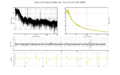
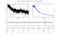
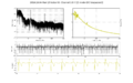
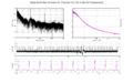
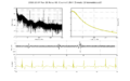
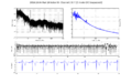
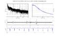
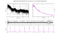
Tested how the difference only mode compares to the difference/sum mode in terms of field sensitivity. Both measurements were taken with the same polarimeter board.
When the polarimeter is balanced, the probe sensitivity in both modes is the same. When the polarimeter is misaligned, the noise in 0-10 Hz band increases for the difference-only polarimeter, but not for the difference/sum polarimeter. In overall, the noise floor for difference/sum polarimeter is really good and the probe noise level drops rapidly in 0-0.5 Hz band.
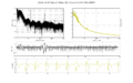
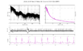
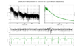
Small polarimeter imbalance
Difference between channels' light powers is 1.4 μW.

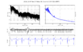
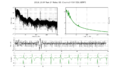
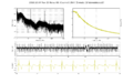
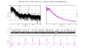
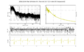
Large polarimeter imbalance
Difference between channels' light powers is 6 μW.

10/26/2016
Pregnant patient in WIMR
Measured a pregnant patient in WIMR. Although all channels worked properly and probe sensitivity was 1 fT/sqrt(Hz), we didn't get any good data, and couldn't see the fMCG signal at all. Maybe there were large field gradients that we didn't properly get rid of, like from wires in a bra or other clothes. The patient returns on November, 14th.
Added a real-time fMCG preview into the FPGA so that we don't end up in this situation again.
10/27/2016
Pulse-density modulation
Implemented delta-sigma PDM (pulse-density modulation) for the FPGA. Now the FPGA can output "analog" control signals from the digital outputs, which our FPGA has plenty of. This would allow us to control every sensor shell coil on all three axis, and permit us to feedback on the field to keep all the sensors in average zero field and thus extend the dynamic range of our measurements. The signal to noise ratio in 0-1 kHz range is surprisingly good, and is around 100 dB. The VI is configured to output the "analog" levels with 16 bit precision. The switching rate is 20 MHz, with the CLK output.
We want to drive the atoms with the high-frequency signal and have them act as the low-pass filter. Mike built a current supply for the coils that reverses the polarity of the coil current for 0 and 1 logical levels.
It would be great to replace the analog inputs with digital signals as well. This would permit us to use a bigger FPGA (NI PXIe-7971R) that could drive as many as 25 sensors. Texas Instruments has Verified Designs section, that explains how to design and layout ADC circuits. File:TI ADC design ECG.pdf
Group meeting
Thad is concerned that the excessive noise in our measurement could have been caused by the probe power noise. We need to modulate the pump power and see how in affects the measured field.