Lena/Oct 2016: Difference between revisions
ElenaZhivun (talk | contribs) |
ElenaZhivun (talk | contribs) |
||
| Line 115: | Line 115: | ||
There are two main approaches we can use. The first approach is to have multiple FPGAs, each one controlling a set of four magnetometers. The cheapest NI FPGA (7851R) costs $2.8k, equating is $700/channel. The drawback is that the FPGA only has 8 analog inputs and 8 analog outputs, and there are no analog outputs free for the feedback signals. There are still free digital outputs that the FPGA can use to talk to an Arduino over SPI or something similar. Using FPGAs will result in the fastest feedback with proper timing. We don't have the requirements for the feedback to be fast (its band is DC-0.5 Hz as of now) With the signal normalization the FPGA is already close to its limit of slices. |
There are two main approaches we can use. The first approach is to have multiple FPGAs, each one controlling a set of four magnetometers. The cheapest NI FPGA (7851R) costs $2.8k, equating is $700/channel. The drawback is that the FPGA only has 8 analog inputs and 8 analog outputs, and there are no analog outputs free for the feedback signals. There are still free digital outputs that the FPGA can use to talk to an Arduino over SPI or something similar. Using FPGAs will result in the fastest feedback with proper timing. We don't have the requirements for the feedback to be fast (its band is DC-0.5 Hz as of now) With the signal normalization the FPGA is already close to its limit of slices. |
||
The second approach is to use a PXI rack with stacks of ADCs and DAQs. The advantage is that we can add DAQs very easily by adding new boards. We could use a dedicated real-time controller to process the data, and if both DAQs and ADCs support NI DAQmx then the real time controller is not really needed. These boards have their own controllers that ensures timing, and the data processing can be done on the host computer. Each sensor running at 20 kHz with 18-32 bit resolution should produce around 1 MBit/second of data, which is very manageable. |
The second approach is to use a PXI rack with stacks of ADCs and DAQs. The advantage is that we can add DAQs very easily by adding new boards. We could use a dedicated real-time controller to process the data, and if both DAQs and ADCs support NI DAQmx then the real time controller is not really needed. These boards have their own controllers that ensures timing, and the data processing can be done on the host computer. Each sensor running at 20 kHz with 18-32 bit resolution should produce around 1 MBit/second of data, which is very manageable. With a dedicated controller the price would be $500/channel, and if the host does the data processing it's $230/channel. |
||
Revision as of 17:04, 13 October 2016
October 2016
BACK/NEXT
10/03/2016
fMCG setup TODO
- Feedback system to keep the fields from "running away". Only the main XYZ fields need to be stabilized, the gradients don't change much day to day
- Reduce the polarimeter noise when misbalanced
Eliminating polarimeter noise when misbalanced
The existing current amplifier consists of two photodiodes connected in a way to add or subtract their photocurrents. The output of this passive circuit is connected to an SR570 current preamplifier.

I want to replace this circuit with something that can output both sum and difference, so that the common mode variations can be cancelled. Apparently a circuit that is supposed to do that has already been designed (see the link). The circuit has very little documentation and needs to be modified to increase the gain. We need 1-2 μA/V on the differential channel and 100-200 μA/V on the sum channel.
10/06/2016
New photodetector
Started on the new photodetector design and prototype here.
Lab meeting
Quick division
FPGA has hard times dividing numbers. Matt mentioned that there is an algorithm that quickly inverts any int32 number by multiplying it with a "magic number". https://en.wikipedia.org/wiki/Fast_inverse_square_root Never mind, it's for the floating point numbers.
fMCG setup field stabilization
Zack and Mike tried to stabilize the field in the magnetically shielded room by controlling the room coils with a feedback look (Y direction only). They tried the fluxgate, but it's sensitivity is not enough, as the polarization rotation signal is going offscreen. The stabilization system works well when the magnetometer signal on the Y channel is used for the feedback control. The bandwidth of the feedback is DC-0.5 Hz. The only problem is that when the sensor is tilted it doesn't work as well.
Shot noise limit for 10 USD
Thad mentioned there is an article by Hobbs titled "Reaching the shot noise limit for $10". File:Shotnoise opn.pdf
Downsample the magnetometer signal to 1 kHz
Zach mentioned that all the existing post-processing software expects the data to be sampled at 1 kHz. Right now it's at 20 kHz, and it's causing problems.
10/10/2016
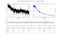
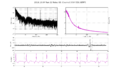
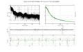
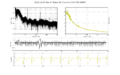
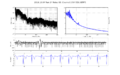
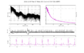
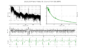
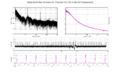
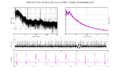
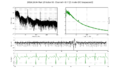
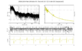
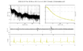
Zach made an adult measurement with all four channels running. The large signal towards the end is Zack adjusting the field.
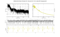
DC run 1
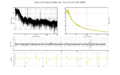
Channel 1
Channel 2
Channel 3
Channel 4


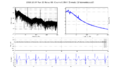
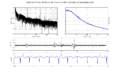
DC run 2
Channel 1
Channel 2
Channel 3
Channel 4


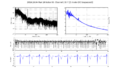
Z mode run 1
Channel 1Y
Channel 1X
Channel 2Y
Channel 2X
Channel 3Y
Channel 3X
Channel 4Y

Channel 4X


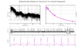
Z mode run 2
Channel 1Y
Channel 1X
Channel 2Y
Channel 2X
Channel 3Y
Channel 3X
Channel 4Y

Channel 4X


10/12/2016
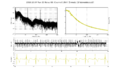
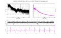
Discrepancy between the expected and measured DAQ noise
It seems like the noise we are measuring is somewhat lower than what our bit depth suggests. With 16 bit ADC and downsampling from 500 ksps to 180 sps, we should have effective 21.8 bit resolution. The DAC range is ±10V and the magnetometer gain is 26 μV/fT, so the resolution should be 0.2 fT at DC. The noise on the PSD goes below 0.1 fT:

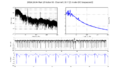
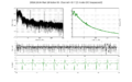
Ripples
There are some ripples on the magnetometers calibration. They might be caused by the windowing.
Adding an anti-aliasing filter to the polarimeter
In order to run the data acquisition at a smaller rate, we can place a hardware anti-aliasing filter on the differential polarimeter boards. This would take the computational load off the digital system and relax the requirements on how fast we acquire the data. Mike suggests replacing adding an active two-pole filter at the output of the polarimeter board. We can place a quad OP140 on the board instead of the dual version. The filter design is described in Horowitz and Hill in CH5.07 page 274. We would need to try different filters to see which one works best for our signal.
Expanding the number of channels
I checked the National Instruments website to see what equipment we might need to expand the number of channels. Each channel requires two analog inputs (Differential and sum polarimeter signals) and two analog outputs (chirp/calibration signal and Z-modulation). We could save one AI by only recording the difference signal, or add one AO if we want to modulate the field along two axes and get three-axial output. We potentially want a digital feedback on X, Y fields as well.
There are two main approaches we can use. The first approach is to have multiple FPGAs, each one controlling a set of four magnetometers. The cheapest NI FPGA (7851R) costs $2.8k, equating is $700/channel. The drawback is that the FPGA only has 8 analog inputs and 8 analog outputs, and there are no analog outputs free for the feedback signals. There are still free digital outputs that the FPGA can use to talk to an Arduino over SPI or something similar. Using FPGAs will result in the fastest feedback with proper timing. We don't have the requirements for the feedback to be fast (its band is DC-0.5 Hz as of now) With the signal normalization the FPGA is already close to its limit of slices.
The second approach is to use a PXI rack with stacks of ADCs and DAQs. The advantage is that we can add DAQs very easily by adding new boards. We could use a dedicated real-time controller to process the data, and if both DAQs and ADCs support NI DAQmx then the real time controller is not really needed. These boards have their own controllers that ensures timing, and the data processing can be done on the host computer. Each sensor running at 20 kHz with 18-32 bit resolution should produce around 1 MBit/second of data, which is very manageable. With a dedicated controller the price would be $500/channel, and if the host does the data processing it's $230/channel.