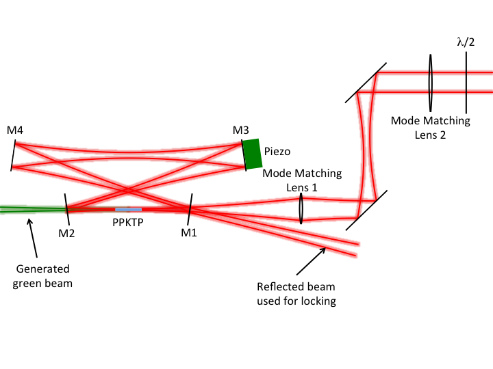
SHG Cavity
We can write our observations and procedures for the SHG cavity here. Also, it might be useful to have a list of any spec sheets.
Measurements
5/21/14
Today the cavity was working well. After alignment I was getting 10 mW of green from 65 mW of IR (15.4% efficiency).
5/21/14
After detuning the temperature and aligning the vertically polarized light to the cavity we saw 5.5 mW of green light. The input power was 45 mW.
Alignment Procedures
The first thing to do is to measure the beam profile and figure out what sort of lenses need to be used to mode match the beam. From what I've experienced, it's easiest to mode match the cavity with two lenses. Both lenses together determine the waist size and position and both need to be adjusted to best mode match the cavity. However, it seems like lens 1 moves the position of the waist more than the size of the waist and lens 2 changes the waist size more than the position. I find it easiest to have both lenses on translation stages.
Once the position and focal lengths of the mode matching lenses are determined, the next thing to do is to place the crystal in the beam path where it will be in the cavity. Use the two walk mirrors to center the beam as best as possible on the crystal. It is possible to see where the beam is hitting each face of the crystal with the IR viewer. Make sure the beam going strait through the crystal and isn't reflecting off of the side of the crystal housing. Also make sure to keep the mode matching lenses as centered on the beam as possible. It is easiest to initially align the cavity if a scale print out of the beam path is taped on the table.
Place the output mirror (M2) and M3 where they should be according to the beam path layout. It is important to have the beam centered on the curved mirrors so that the mirror doesn't have to be tilted at an extreme angle to align the cavity. Use M2 and M3 to walk the beam along the beam path layout. Make sure it is also the right height off of the table.
Next place M4 and M1 in the beam path. Again, make sure the beam is as centered as possible on the curved mirror. Use these mirrors to shine the beam through the crystal again. If you were careful enough while placing the mirrors in the cavity you should be able to see at least one other dot (probably several dots) by the reflected beam or the generated green beam. While looking at those dots, walk M4 and M1 to try to overlap the dots with the reflected beam. As you get more aligned you should see more dots begin to collapse in on the central spot.
Pro Tip: If the reflected beam is so bright that it is tough to see the multiple passes and you can't see a transmitted beam through one of the cavity mirrors, put a microscope slide in the long leg of the cavity and use the reflection off of that to see the multiple passes. After you align the cavity this way and remove the slide, you will need to tweak the alignment a little, but not an obnoxious amount.
Once the dots are well enough aligned and the piezo ramp isn't too fast, it should be possible to see the light in the cavity blinking. The cavity peaks should be visible if the reflected beam or a transmitted beam is looked at with a photodiode. Walk M1 and M4 or M2 and M3 to optimize the peaks. M2 and M3 determine the beam path inside the cavity and M1 and M4 are used to overlap the beam onto that path. In my experience M2 and M3 are more sensitive than M1 and M4. Adjusting the position of lens 1 and lens 2 will also be necessary to get the input beam focused in the correct spot. Be careful adjusting the mirrors that walk the beam into the cavity so that the input beam isn't walked off of the crystal.
In order to generate the most green the cavity needs to be tuned for 1055 nm light at the correct polarization. The best way to do this is to optimize the polarization so that the most green is generated, then detune the temperature (~2 degrees C should be enough). The generated green beam should decrease in intensity. Now by looking at a transmitted IR beam, the cavity can be optimized for the IR wavelength that needs to be doubled.
After the initial set up the cavity can be aligned by blocking the cavity and making sure the input beam is going through the center of the crystal, then walking the mirror diagonal mirror pairs adjusting the position of the mode matching lenses iteratively.
Once the IR peaks are optimized, the crystal temperature can be properly tuned. The output should be a bright green beam that can be easily locked (as described below). The locking scheme being used is the Hanch Couillaud method. This method requires a polarization selecting element in the cavity (in this case the PPKTP crystal) and an input beam that has a polarization at some angle to the resonant polarization. For this reason the polarization of the input beam will need to be slightly rotated from the optimal angle.
- Matlab program for mode matching?
Locking Circuit
- Circuit diagram
- Procedures for getting a clean error signal
- Procedures for locking
- Troubleshooting the circuit when lock isn't working well?
