Project lead: Stephen Eick
Purpose
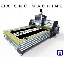
The purpose of this project is to provide Garage Physics with a low-cost, high-quality CNC router.
Introduction
The CNC router to be constructed is the OX. This particular 3-axis (X, Y, and Z) router was selected due to its relatively-low cost, sturdiness, and flexible build size.
Hardware
Item |
Quantity |
Part Link |
Item |
Quantity |
Part Link |
V-Slot 20x80mm (1500) |
2 |
V-Slot 20x60mm (1500) |
2 |
||
V-Slot 20x40mm (1500) |
4 |
V-Slot 20x40mm (250) |
1 |
||
Solid V Wheel Kit |
28 |
90 Degree corner bracket |
8 |
||
5 hole 90 degree joining plate |
4 |
Universal L brackets (double) |
4 |
||
Aluminum Spacers (1-1/2") |
3 |
Precision Shim |
40 |
||
Eccentric Spacers (1/4" Full Size) |
13 |
Threaded Rod Plate (Nema 17) |
2 |
http://openbuildspartstore.com/threaded-rod-plate-for-nema-17-stepper-motor/ |
|
Flexible Coupling (5mm x 8mm) |
1 |
8mm Threaded Rod (250mm) |
1 |
||
Lock Collar (8mm) |
2 |
Bearing (8mm) |
1 |
||
GT3 Timing Belt |
7 |
Socket Head M5 Screws (65mm) |
1 |
||
OX Plates |
1 |
Acme Nut Block 8mm |
1 |
http://openbuildspartstore.com/nut-block-for-8mm-metric-acme-lead-screw/ |
|
GT3 Timing Pulley |
3 |
http://openbuildspartstore.com/gt3-aluminum-timing-pulley-20-tooth/ |
M5x15mm Low Profile Screws |
2 |
|
M5x30mm Low Profile Screws |
2 |
M5x45mm Low Profile Screws |
1 |
||
M5x8mm Low Profile Screws |
2 |
M5x20mm Low Profile Screws |
1 |
||
M3x45mm Cap Head Screws |
4 |
5mm Locknut |
12 |
||
M5 Tee Nuts |
2 |
1/8" Spacers |
12 |
||
1/4" Spacers |
17 |
V-Slot Spacer Block |
2 |
Electronics
Still under development...
Item |
Link |
Nema 23 Stepper |
|
Nema 17 Stepper |
|
Stepper Driver Boards |
https://www.servo2go.com/product.php?ID=100434&cat=10021&sub=10003 |
12V/30A PSU |
http://openbuildspartstore.com/12v-30a-power-supply/ |
40x40mm x 10 12v fan |
http://www.amazon.com/dp/B000LB0M8S/ref=cm_sw_su_dp |
||Cable ||http://openbuildspartstore.com/16-2-project-wire/ ||dgerloop.slack.com/
Controlling the router
A Single Stepper
The first order of business is achieving control of a single stepper motor. Here's a bunch of links that were very useful while working through this:
https://www.servo2go.com/support/downloads/3540MUserManual.pdf
Connecting the stepper to the driver board (see page 9)
Stepper motor ratings (see page 17)
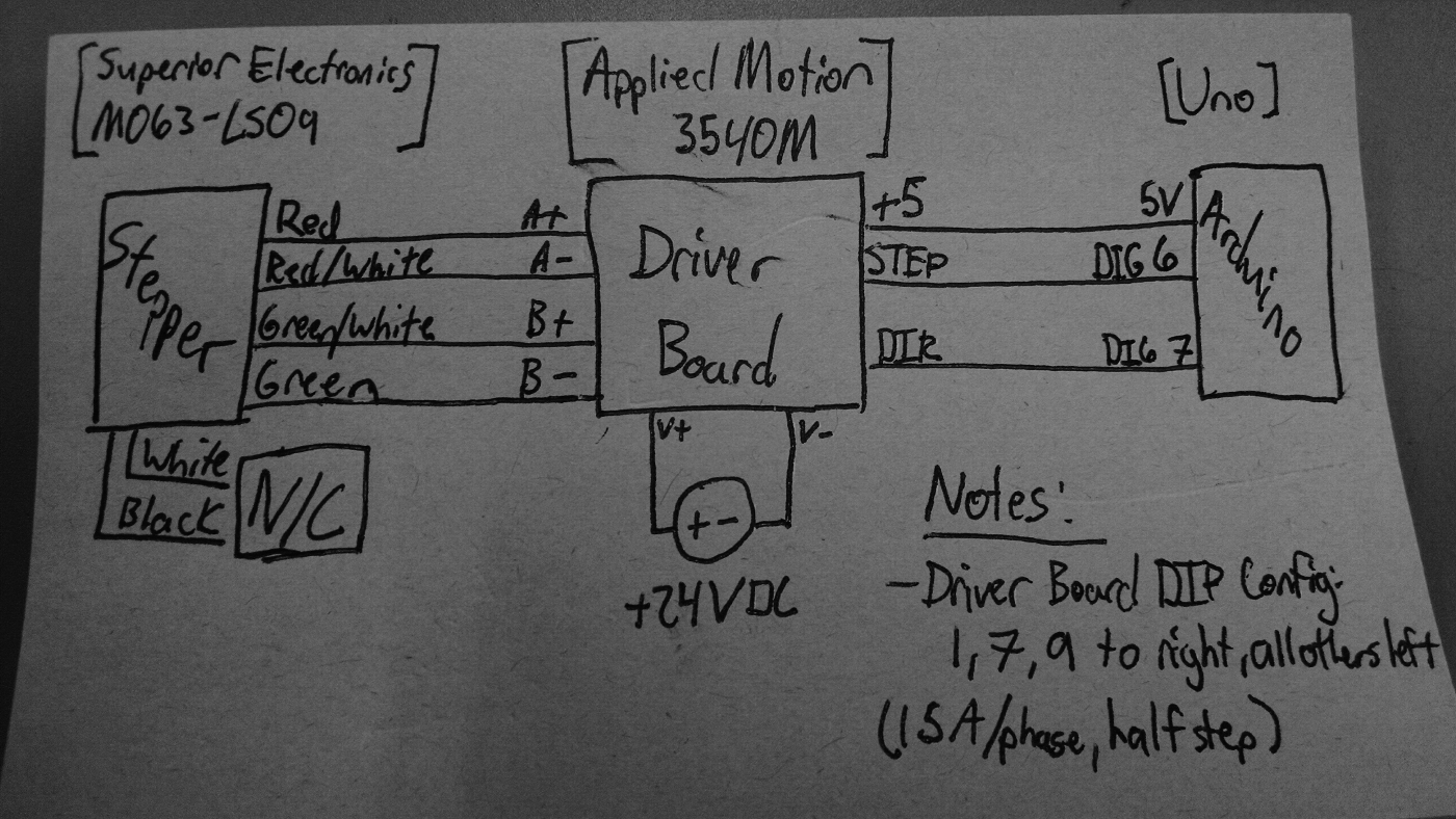
Here's a block diagram of the test setup used:

Some of the quirks discovered in testing:
- The safe stepping period range is 300-1200 microseconds.
Starting the stepper at a power-up with a stepping period of <300us does not work.
- The stepper was able to operate down to 200us by progressively lowering the period. If power is always maintained, then one could potentially operate the stepper at that fast of a stepping frequency.
- Above 1200us, the stepper experiences severe vibrations. Mounting it to a bracket should solve this.
- The driver board was configured to use 1.5A/phase and half-stepping.
Coming sort of soon...
Operating the router
Coming not too soon...