|
Size: 1648
Comment:
|
Size: 3695
Comment:
|
| Deletions are marked like this. | Additions are marked like this. |
| Line 2: | Line 2: |
| ||<:30%>[:PiraScheme#Mechanics: Table of Mechanics Demonstration]||<:30%>[:MEEquipmentList: List of Mechanics Equipment & Supplies]||<:30%>[:Demonstrations:Lecture Demonstrations]|| | ||<30% style="text-align:center">[[PiraScheme#Mechanics|Table of Mechanics Demonstration]] ||<30% style="text-align:center">[[MEEquipmentList|List of Mechanics Equipment & Supplies]] ||<30% style="text-align:center">[[Demonstrations|Lecture Demonstrations]] || |
| Line 4: | Line 4: |
| = Demo Name, PIRA# = | |
| Line 6: | Line 5: |
| = Ladder Against a Wall, 1K10.20 = | |
| Line 7: | Line 7: |
| Applications of Newton's Laws, [:AppNewtonsLaws#DynamicTorque: 1K10. Dynamic Torque] | . Applications of Newton's Laws, [[AppNewtonsLaws#DynamicTorque|1K10. Dynamic Torque]] '''pira200 Listed''' |
| Line 10: | Line 13: |
| * '''Cabinet:''' [:MechanicsCabinet:Mechanic (ME)] * '''Bay:''' [:MechanicsCabinetBayA1:(A1)] * '''Shelf:''' #1,2,3.. |
|
| Line 14: | Line 14: |
| attachment: mainPhoto | * '''Cabinet:''' [[MechanicsCabinet|Mechanic (ME)]] * '''Bay:''' C7 {{attachment:Ladder01-400.jpg}} |
| Line 19: | Line 22: |
||<:style="width: 60%" :40%>'''Equipment'''||<:30%>'''Location'''||<:25%>'''ID Number'''|| |
||<40% style="" ;text-align:center">'''Equipment''' ||<30% style="text-align:center">'''Location''' ||<25% style="text-align:center">'''ID Number''' || |
| Line 22: | Line 24: |
| ||apparatus||[:MechanicsCabinetBayB1: ME, Bay B1, Shelf #2]|| || ||all other parts||[:MechanicsCabinetBayB1: ME, Bay B1, Shelf #2]|| || ||...||[:MechanicsCabinetBayA5: ME, Bay A5, Shelf #2]|| || |
||Ladder & Wall ||ME, Bay C7 || || ||3/4" & 1/2" Rod with Clamps ||Rod and Tackle Cabinets Located Near Main Lecture Halls || || ||Weights ||[[MechanicsCabinetBayA1|ME, Bay A1, Shelf #5]] || || |
| Line 27: | Line 29: |
| '''''Important Setup Notes:''''' * N/A |
|
| Line 31: | Line 31: |
| '''Setup and Procedure:''' | '''''Important Setup Notes:''''' |
| Line 33: | Line 33: |
| 1. List steps for setup then procedure. 1. ... |
* N/A '''Setup and Procedure:''' 1. Vertically mount a 3/4" rod to a lecture bench with a table clamp. 1. Another clamp attached to this rod will hold the 1/2" rod horizontally. 1. There are two parallel holes on one end of the wall (board). The 1/2" rod will slide through these to hold up the wall. 1. Adjust the height of the rod by sliding the clamp up and down the vertical rod. The height needs to be at the point where the bottom wall meets the table top. 1. Lean the ladder against the wall at some angle with respect to the ground. The smaller the angle, the more unstable the ladder will be as we move the weight up the rungs (next step). 1. Hang the weight off the bottom rung, and see if the ladder stays in place. If it does, keep moving the weight up rung by rung until either the ladder slides to the ground or the top rung is reached. 1. If desired, repeat the process for a different angle or using a heavier/lighter weight. |
| Line 37: | Line 46: |
| Line 39: | Line 49: |
| '''Discussion:''' | |
| Line 40: | Line 51: |
| '''Discussion:''' | A ladder against a wall forms a rotational system. Typically we want this system to be static, especially when there's a person climbing the ladder (i.e. we don't want the ladder to slide out from under the person). All of the forces acting on the ladder are represented in the free body diagram below. |
| Line 42: | Line 53: |
| Discuss the physics behind the demonstration, explaining some of the various steps of the demonstration when appropriate. | {{attachment:LadderFBD-250.jpg}} |
| Line 44: | Line 55: |
| ||attachment: photo||attachment: photo||attachment: photo||attachment: photo|| | The ladder will remain in place as long as the net force and net torque acting on it are zero. As the weight moves up the ladder, the torque due to this weight increases causing the torque due to the static friction on the feet of the ladder to increase. The maximum amount of static friction that can be supplied is equal to μ,,S,,·N where μ denotes the coefficient of static friction and N is the normal force due to the ground acting on the feet of the ladder. Once the maximum is reached, and additional torque due to the weight will cause the ladder to slip out away from the wall. || {{attachment:Ladder03-250.jpg}} || {{attachment:Ladder04-250.jpg}} || {{attachment:Ladder06-250.jpg}} || {{attachment:Ladder07-250.jpg}} || || {{attachment:Ladder09-250.jpg}} || {{attachment:Ladder10-250.jpg}} || {{attachment:Ladder12-250.jpg}} || {{attachment:Ladder13-250.jpg}} || |
| Line 47: | Line 63: |
| * [https://www.youtube.com/user/LectureDemostrations/videos?view=1 Lecture Demonstration's Youtube Channel] | * [[https://www.youtube.com/user/LectureDemostrations/videos?view=1|Lecture Demonstration's Youtube Channel]] |
| Line 51: | Line 68: |
| * [https://en.wikipedia.org/wiki/Torque Wikipedia - Torque] | * [[https://en.wikipedia.org/wiki/Torque|Wikipedia - Torque]] |
| Line 53: | Line 70: |
[:Instructional:Home] |
[[Instructional|Home]] |
Ladder Against a Wall, 1K10.20
Topic and Concept:
Applications of Newton's Laws, 1K10. Dynamic Torque
pira200 Listed
Location:
Cabinet: Mechanic (ME)
Bay: C7
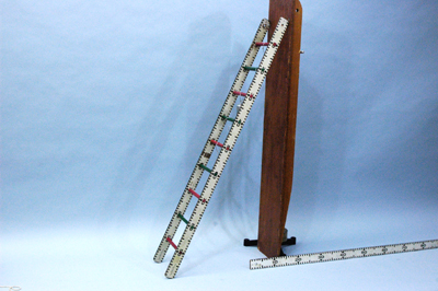
Abstract:
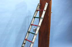
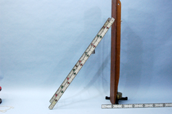
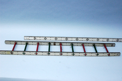
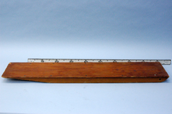
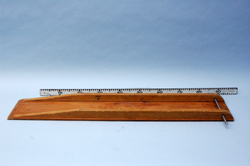
A model ladder is set to lean against a wall. A weight is then moved up one rung at a time.
Equipment |
Location |
ID Number |
|
|
|
Ladder & Wall |
ME, Bay C7 |
|
3/4" & 1/2" Rod with Clamps |
Rod and Tackle Cabinets Located Near Main Lecture Halls |
|
Weights |
|
Important Setup Notes:
- N/A
Setup and Procedure:
- Vertically mount a 3/4" rod to a lecture bench with a table clamp.
- Another clamp attached to this rod will hold the 1/2" rod horizontally.
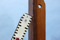
- There are two parallel holes on one end of the wall (board). The 1/2" rod will slide through these to hold up the wall.
- Adjust the height of the rod by sliding the clamp up and down the vertical rod. The height needs to be at the point where the bottom wall meets the table top.
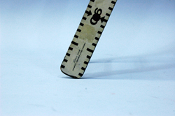
- Lean the ladder against the wall at some angle with respect to the ground. The smaller the angle, the more unstable the ladder will be as we move the weight up the rungs (next step).
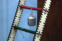
- Hang the weight off the bottom rung, and see if the ladder stays in place. If it does, keep moving the weight up rung by rung until either the ladder slides to the ground or the top rung is reached.
- If desired, repeat the process for a different angle or using a heavier/lighter weight.
Cautions, Warnings, or Safety Concerns:
- N/A
Discussion:
A ladder against a wall forms a rotational system. Typically we want this system to be static, especially when there's a person climbing the ladder (i.e. we don't want the ladder to slide out from under the person). All of the forces acting on the ladder are represented in the free body diagram below.
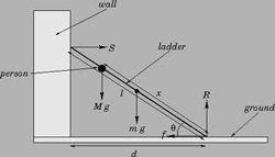
The ladder will remain in place as long as the net force and net torque acting on it are zero. As the weight moves up the ladder, the torque due to this weight increases causing the torque due to the static friction on the feet of the ladder to increase. The maximum amount of static friction that can be supplied is equal to μS·N where μ denotes the coefficient of static friction and N is the normal force due to the ground acting on the feet of the ladder. Once the maximum is reached, and additional torque due to the weight will cause the ladder to slip out away from the wall.
|
|
|
|
|
|
|
|
Videos:
References:
