|
Size: 1664
Comment:
|
Size: 3199
Comment:
|
| Deletions are marked like this. | Additions are marked like this. |
| Line 16: | Line 16: |
| attachment: mainPhoto | {{attachment:GravitationalLens.JPG}} |
| Line 20: | Line 20: |
| Insert succinct description of demonstration. | Lens made in 2007 by Sara Yaeger of the UW Physics Instrument Shop from PMMA (a.k.a. Lucite, Plexiglass, Perspex, etc; n=1.495), using a lathe. Lens profile calculated by Jim Reardon, based on C. Darwin, "The Gravity Field of a Particle", Proc. Roy. Soc. A '''249''', 180 (1959), especially section 8, culminating in equation 29, which gives the deviation of the ray as a function of perihelion distance. Similar calculations presented in J. Higbie, "Gravitational Lens", Am. J. Phys '''49''', 652 (1981). Looking through the lens from a viewpoint on the lens axis with the flat side facing the viewer, the lens causes incoming light rays to deviate by the same amount as would be caused by a black hole with mass m=2.595 x 10^24 kg (a little less than half the mass of the Earth). This mass was chosen in order that light with an impact parameter of 1 cm would be captured into the "light ring". The radius of the light ring would be 0.5774 cm. The event horizon of such a black hole would have a radius of 0.3849 cm. |
| Line 23: | Line 33: |
| ||apparatus ||[[MechanicsCabinetBayB1|ME, Bay B1, Shelf #2]] || || ||all other parts ||[[MechanicsCabinetBayB1|ME, Bay B1, Shelf #2]] || || ||... ||[[MechanicsCabinetBayA5|ME, Bay A5, Shelf #2]] || || |
||apparatus ||[[OpticsCabinetBayA1|OP, Bay A1, Shelf #2]] || || ||light source ||[[CabinetNextToElevator|Cabinet Next to Elevator, Top half, Shelf #1]] || || |
| Line 30: | Line 39: |
| '''''Important Setup Notes:''''' * ''''' ''''' |
|
| Line 36: | Line 41: |
| 1. List steps for setup then procedure. 1. ... |
The lens can be used to engage and excite an audience, to gain intuition about how gravity affects light, or to observe Einstein Rings (see photo below). |
| Line 39: | Line 43: |
| '''Cautions, Warnings, or Safety Concerns:''' | Of note is that partial Einstein rings may be observed even if the observer, lens and source are only very roughly coaxial--alignment does not need to be perfect. |
| Line 41: | Line 45: |
| * | . {{attachment:EinsteinRing.JPG}} |
| Line 45: | Line 49: |
| Discuss the physics behind the demonstration, explaining some of the various steps of the demonstration when appropriate. ||attachment: photo ||attachment: photo ||attachment: photo ||attachment: photo || |
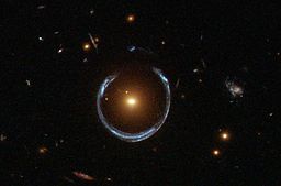
The best current example of an actual Einstein ring is that caused by the luminous red galaxy LRG 3-757 (Hubble Space Telescope photo courtesy of NASA): |
| Line 48: | Line 51: |
| {{attachment:LRG3-757.jpg}} | |
| Line 49: | Line 53: |
| The flat spot in the center of the lens profile is set by the thickness of the original piece of Perspex, and has no physical significance. | |
| Line 57: | Line 61: |
| * List any references | * C. Darwin, "The Gravity Field of a Particle", Proc. Roy. Soc. A '''249''', 180 (1959), especially section 8, culminating in equation 29, which gives the deviation of the ray as a function of perihelion distance; * J. Higbie, "Gravitational Lens", Am. J. Phys '''49''', 652 (1981) |
Gravitational Lens, 8C20.40
Topic and Concept:
- General Relativity
Location:
Cabinet: Optics (OP)
Bay: (A1)
Shelf: #1
Abstract:
Lens made in 2007 by Sara Yaeger of the UW Physics Instrument Shop from PMMA (a.k.a. Lucite, Plexiglass, Perspex, etc; n=1.495), using a lathe.
Lens profile calculated by Jim Reardon, based on C. Darwin, "The Gravity Field of a Particle", Proc. Roy. Soc. A 249, 180 (1959), especially section 8, culminating in equation 29, which gives the deviation of the ray as a function of perihelion distance. Similar calculations presented in J. Higbie, "Gravitational Lens", Am. J. Phys 49, 652 (1981).
Looking through the lens from a viewpoint on the lens axis with the flat side facing the viewer, the lens causes incoming light rays to deviate by the same amount as would be caused by a black hole with mass m=2.595 x 10^24 kg (a little less than half the mass of the Earth).
This mass was chosen in order that light with an impact parameter of 1 cm would be captured into the "light ring".
The radius of the light ring would be 0.5774 cm.
The event horizon of such a black hole would have a radius of 0.3849 cm.
Equipment |
Location |
ID Number |
|
|
|
apparatus |
|
|
light source |
|
Setup and Procedure:
The lens can be used to engage and excite an audience, to gain intuition about how gravity affects light, or to observe Einstein Rings (see photo below).
Of note is that partial Einstein rings may be observed even if the observer, lens and source are only very roughly coaxial--alignment does not need to be perfect.
Discussion:
The best current example of an actual Einstein ring is that caused by the luminous red galaxy LRG 3-757 (Hubble Space Telescope photo courtesy of NASA):

The flat spot in the center of the lens profile is set by the thickness of the original piece of Perspex, and has no physical significance.
Videos:
References:
C. Darwin, "The Gravity Field of a Particle", Proc. Roy. Soc. A 249, 180 (1959), especially section 8, culminating in equation 29, which gives the deviation of the ray as a function of perihelion distance;
J. Higbie, "Gravitational Lens", Am. J. Phys 49, 652 (1981)