|
Size: 2924
Comment:
|
Size: 4411
Comment:
|
| Deletions are marked like this. | Additions are marked like this. |
| Line 11: | Line 11: |
| * '''Bay:''' [[ThermoCabinetBayA1|(A1)]] * '''Shelf:''' #1,2,3.. |
* '''Bay:''' [[ThermoCabinetBayA1|(A1)]]? * '''Shelf:''' #1,2,3.. ? |
| Line 14: | Line 14: |
| {{attachment: BreakBolt01-400.jpg}} | {{attachment:BreakBolt01-400.jpg}} |
| Line 21: | Line 22: |
| ||apparatus||[[ThermoCabinetBayB1| TD, Bay B1, Shelf #2]]|| || ||all other parts||[[ThermoCabinetBayB1| TD, Bay B1, Shelf #2]]|| || ||...||[[ThermoCabinetBayA5| TD, Bay A5, Shelf #2]]|| || |
||Main stand||[[ThermoCabinetBayB1| TD, Bay B1, Shelf #2]]??|| || ||Green wood blocks||[[ThermoCabinetBayB1| TD, Bay B1, Shelf #2]]|| || ||Burner with attached air hose|| || || ||Matches|| || || ||Mallet|| || || ||0.5 L liquid nitrogen|| || || ||Safety glasses and gloves ||[[RedWhiteGasCart|Red and white gas cart]]||Rooms 2103, 2241, (and 2223 upon request)|| || |
| Line 32: | Line 38: |
1. List steps for setup then procedure. 1. ... |
1. Slide the iron bolt through the three holes. You may have to fiddle with the wedge-shaped piece of metal so that the middle hole lines up with the outer ones. 1. Place the stand on the green wood blocks. 1. To light the burner, connect the attached gas hose to the gas out (red panel) on the [[RedWhiteGasCart|red and white gas cart]]. 1. Open the gas valve. 1. Light a match and bring it near the top of the burner. 1. The flame will ignite the gas. Adjust the flame height accordingly by adjusting the valve. 1. Place the lit burner beneath the middle bar (see photos). 1. As the bar expands you will need to hammer down the metal wedge. Keep heating until the wedge is all of the way down and the top pin is in contact with the stand. 1. Turn off the flame by closing the gas valve. 1. Pour liquid nitrogen on the middle bar in small splashes until the bar contracts enough to break the iron bolt. |
| Line 44: | Line 57: |
| Discuss the physics behind the demonstration, explaining some of the various steps of the demonstration when appropriate. | As the middle bar is heated, its length expands in accordance with the equation ΔL/L = α,,L,,*ΔT where L is the initial length, ΔL is the change in length, α,,L,, is the linear expansion coefficient of the material, and ΔT is the change in temperature of the material. The adjustable wedge on the back part of the bar allows this expansion to occur away from the iron bolt. When we remove the heat source and cool the bar with liquid nitrogen, the bar contracts putting a sheering force on the bolt that is greater than what it can handle. |
Break the Bolt, 4A30.30b
Topic and Concept:
Thermal Properties of Matter, 4A30. ThermalExpansion
Location:
Cabinet: Thermodynamics (TD)
Bay: (A1)?
Shelf: #1,2,3.. ?
Abstract:
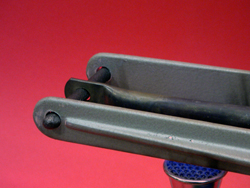
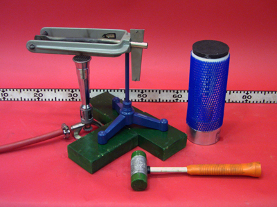
A heated bar is tightened in a yoke against a cast iron peg which breaks as the bar cools.
Equipment |
Location |
ID Number |
|
|
|
Main stand |
|
|
Green wood blocks |
|
|
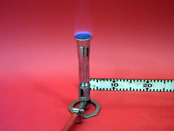
Burner with attached air hose |
|
|
Matches |
|
|
Mallet |
|
|
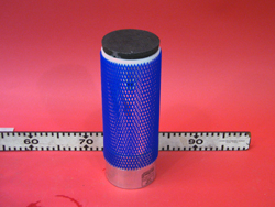
0.5 L liquid nitrogen |
|
|
||Safety glasses and gloves
Rooms 2103, 2241, (and 2223 upon request) |
|
Important Setup Notes:
This demonstration requires a supply of methane gas usually provided by the red and white gas carts found in rooms 2103, 2241, (and 2223 upon request).
- This demonstration requires a supply of liquid nitrogen. The main supply is located at the loading dock. If 12 hours notice given to lecture demo, supply will be provided.
Setup and Procedure:
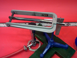
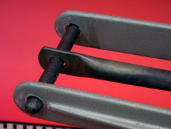
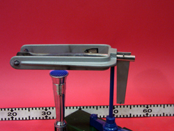
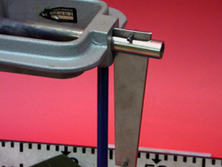
- Slide the iron bolt through the three holes. You may have to fiddle with the wedge-shaped piece of metal so that the middle hole lines up with the outer ones.
- Place the stand on the green wood blocks.
To light the burner, connect the attached gas hose to the gas out (red panel) on the red and white gas cart.
- Open the gas valve.
- Light a match and bring it near the top of the burner.
- The flame will ignite the gas. Adjust the flame height accordingly by adjusting the valve.
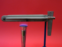
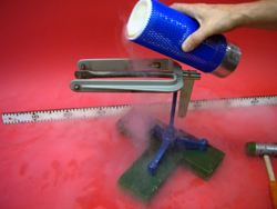
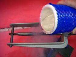
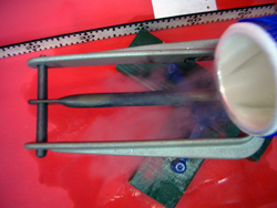
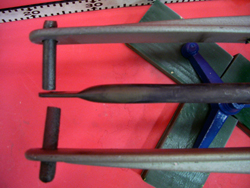
- Place the lit burner beneath the middle bar (see photos).
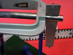
- As the bar expands you will need to hammer down the metal wedge. Keep heating until the wedge is all of the way down and the top pin is in contact with the stand.
- Turn off the flame by closing the gas valve.
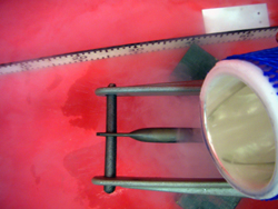
- Pour liquid nitrogen on the middle bar in small splashes until the bar contracts enough to break the iron bolt.
Cautions, Warnings, or Safety Concerns:
- Always use the gloves and safety glasses throughout this demonstration.
- Beware of the heated plate - contact with skin could cause severe burns!
- Use care when working with the liquid nitrogen - prolonged contact with skin causes severe frostbite!
Discussion:
As the middle bar is heated, its length expands in accordance with the equation
ΔL/L = αL*ΔT
where L is the initial length, ΔL is the change in length, αL is the linear expansion coefficient of the material, and ΔT is the change in temperature of the material. The adjustable wedge on the back part of the bar allows this expansion to occur away from the iron bolt. When we remove the heat source and cool the bar with liquid nitrogen, the bar contracts putting a sheering force on the bolt that is greater than what it can handle.
|
|
|
|
|
|
|
|
|
|
|
|
|
|
|
|
Videos:
References:
