|
Size: 1725
Comment:
|
Size: 1844
Comment:
|
| Deletions are marked like this. | Additions are marked like this. |
| Line 8: | Line 8: |
| [[attachment:E-6-200.png|{{attachment:E-6-200.png|attachment:E-6-200.png|width="500 height=138"}}]] | [[attachment:E-6-200.png|{{attachment:E-6-200.jpg|attachment:E-6-200.jpg|width="500 height=138"}}]] |
| Line 11: | Line 11: |
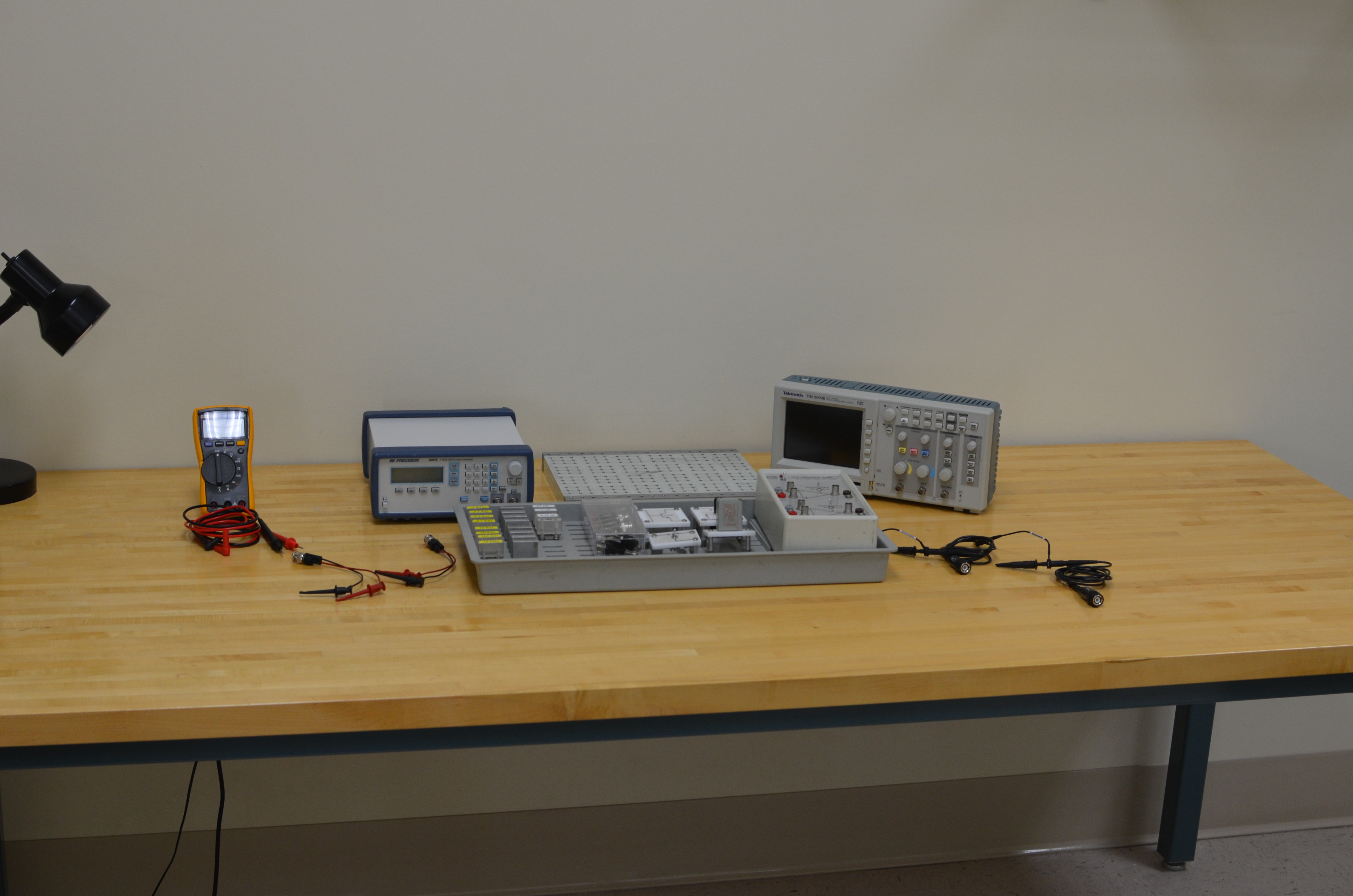
| * 1 [[3323 Shelf-2#Leader_Oscilloscope|Oscilloscope]] * 1 [[3323-2#Kruhn-Hite_Function_Generators|Function Generator]] (Krohn-Hite, Pasco) * 1 [[3323-1#FlukeMultimeter|Fluke 115 Handheld Multimeter]] * w/[[Hanging PASCO Voltage Sensors#Fluke_Multimeter_Sensor|Hanging PASCO Voltage Sensors#Fluke Multimeter Sensor]] |
* 1 [[3323-1#Leader_Oscilloscope|Oscilloscope]] * w/ 2 [[Hanging Oscilloscope Probes#BNC to Alligator Cables|Oscilloscope Probes]] * 1 [[3323-1#Kruhn-Hite_Function_Generators|Function Generator]] * 1 [[3323-2#FlukeMultimeter|Fluke 115 Handheld Multimeter]] * w/[[Hanging PASCO Voltage Sensors#Fluke_Multimeter_Sensor|Fluke Multimeter Probe Set]] * 2 [[3323-3#BNC to Alligator Cables|BNC to Alligator Cable]] |
| Line 23: | Line 25: |
| * Resistor Set (1kΩ, 2.2kΩ, 3.3kΩ, 4.7kΩ, 10kΩ, 20kΩ, 100kΩ, 10MΩ) | * Resistor Set (100Ω, 200Ω, 400Ω, 1kΩ, 2.2kΩ, 3.3kΩ, 4.7kΩ, 10kΩ, 20kΩ, 100kΩ, 10MΩ) |
E-6: Cathode Ray Oscilloscope And Differential Amplifier
Quantity: 39
Contents
Experiment Contents
w/ 2 Oscilloscope Probes
w/Kit
Also
- 1 Oscilloscope Manual
Check
Plug Board Kit (30 Items)
- Resistor Set (100Ω, 200Ω, 400Ω, 1kΩ, 2.2kΩ, 3.3kΩ, 4.7kΩ, 10kΩ, 20kΩ, 100kΩ, 10MΩ)
- 8 Bridge Plugs
- Capacitor Set (47nF, 1μF, 0.47μF)
- Diode
- Inductor (1 H)
- SPDT Switch
- Variable Resistor (1k)
- Transistor (2N1480)
- Differential Amplifier
- Adapter Set (2 Pomona 1269, 2 Pomona 1296, 1 BNC 'T')
Troubleshooting
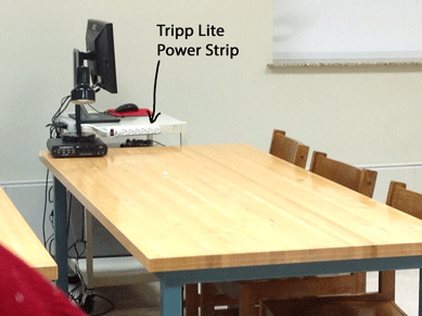
If the output of the differential amplifier is unstable, verify that all E-6 equipment is plugged into the Tripp Lite power strip, which is located adjacent to the lab table (see photo below), and the Tripp Lite power strip is plugged into the wall. No E-6 equipment should be plugged into the power strip on the back of the computer cart, which has a dubious ground (as of 3/10/14).

