|
Size: 1754
Comment:
|
← Revision 5 as of 2018-07-18 16:51:19 ⇥
Size: 3550
Comment:
|
| Deletions are marked like this. | Additions are marked like this. |
| Line 2: | Line 2: |
| ||<:30%>[:PiraScheme#Mechanics: Table of Mechanics Demonstration]||<:30%>[:MEEquipmentList: List of Mechanics Equipment & Supplies]||<:30%>[:Demonstrations:Lecture Demonstrations]|| | ||<30% style="text-align:center">[[PiraScheme#Mechanics|Table of Mechanics Demonstration]] ||<30% style="text-align:center">[[MEEquipmentList|List of Mechanics Equipment & Supplies]] ||<30% style="text-align:center">[[Demonstrations|Lecture Demonstrations]] || |
| Line 5: | Line 6: |
| '''Topic and Concept:''' | |
| Line 6: | Line 8: |
| '''Topic and Concept:''' Statistics of Rigid Bodies, [:RigidBodies#StaticTorque: 1J40. Static Torque] |
. Statistics of Rigid Bodies, [[RigidBodies#StaticTorque|1J40. Static Torque]] '''pira200 Listed''' |
| Line 10: | Line 13: |
| * '''Cabinet:''' [:MechanicsCabinet:Mechanic (ME)] * '''Bay:''' [:MechanicsCabinetBayA1:(A1)] * '''Shelf:''' #1,2,3.. |
|
| Line 14: | Line 14: |
| attachment: mainPhoto | * '''Cabinet:''' [[MechanicsCabinet|Mechanic (ME)]] * '''Bay:''' C1 * '''Shelf:''' T {{attachment:TorqueBeam01-400.jpg}} |
| Line 19: | Line 23: |
||<:style="width: 60%" :40%>'''Equipment'''||<:30%>'''Location'''||<:25%>'''ID Number'''|| |
||<40% style="" ;text-align:center">'''Equipment''' ||<30% style="text-align:center">'''Location''' ||<25% style="text-align:center">'''ID Number''' || |
| Line 22: | Line 25: |
| ||apparatus||[:MechanicsCabinetBayB1: ME, Bay B1, Shelf #2]|| || ||all other parts||[:MechanicsCabinetBayB1: ME, Bay B1, Shelf #2]|| || ||...||[:MechanicsCabinetBayA5: ME, Bay A5, Shelf #2]|| || |
||Torque Beam ||ME, Bay C1, Shelf T || || ||Weights and Weight Hangars ||[[MechanicsCabinetBayA1|ME, Bay BA, Shelf #5]] || || ||3/4" Rod and clamps ||Rod and tackle cabinet near main lecture halls || || |
| Line 27: | Line 30: |
| '''''Important Setup Notes:''''' * N/A |
|
| Line 31: | Line 32: |
| '''Setup and Procedure:''' | '''''Important Setup Notes:''''' |
| Line 33: | Line 34: |
| 1. List steps for setup then procedure. 1. ... |
* N/A '''Setup and Procedure:''' 1. Place apparatus on lecture bench with numbered side facing audience. 1. Behind the apparatus, mount a 3/4" rod to the bench with a table clamp. 1. To this vertical rod, attach another rod horizontally so that it is about above the apparatus, low enough so that the central loop of the beam can slip onto the rod (this is how we will suspend the beam). 1. From each of the outer loops, hang a weight hangar, and load up each with some amount of weight. 1. Choose the relative positions on the beam of the weights so that the beam will balance. 1. The moment of truth: unhook the chain from the stage left leg of the apparatus. Push the legs out to free the beam. If the previous two steps were completed appropriately, the beam will remain balanced. See photos below for some examples of weight - position combinations. |
| Line 37: | Line 46: |
| Line 39: | Line 49: |
| '''Discussion:''' | |
| Line 40: | Line 51: |
| '''Discussion:''' | There are four torques acting on the beam: that due to gravity (weight of the beam), tension of the suspension string, and each of the two weights. If we set our origin at the 50 cm mark, the torque due to gravity and the tension go to zero. For the torques to balance giving us zero angular acceleration (keeping the beam balanced), we must have |
| Line 42: | Line 53: |
| Discuss the physics behind the demonstration, explaining some of the various steps of the demonstration when appropriate. | r,,1,,·W,,1,, = r,,2,,·W,,2,, -> r,,1,,·m,,1,, = r,,2,,·m,,2,, |
| Line 44: | Line 55: |
| ||attachment: photo||attachment: photo||attachment: photo||attachment: photo|| | where the r's denote the distance from the center of the beam of each weight hangar and the m's denote the total mass of the weight hangar. || {{attachment:TorqueBeam02-250.jpg}} || {{attachment:TorqueBeam03-250.jpg}} || {{attachment:TorqueBeam04-250.jpg}} || {{attachment:TorqueBeam05-250.jpg}} || || {{attachment:TorqueBeam06-250.jpg}} || {{attachment:TorqueBeam07-250.jpg}} || {{attachment:TorqueBeam08-250.jpg}} || {{attachment:TorqueBeam09-250.jpg}} || || {{attachment:TorqueBeam10-250.jpg}} || {{attachment:TorqueBeam13-250.jpg}} || {{attachment:TorqueBeam14-250.jpg}} || {{attachment:TorqueBeam15-250.jpg}} || |
| Line 47: | Line 64: |
| * [https://www.youtube.com/user/LectureDemostrations/videos?view=1 Lecture Demonstration's Youtube Channel] | * [[https://www.youtube.com/user/LectureDemostrations/videos?view=1|Lecture Demonstration's Youtube Channel]] |
| Line 51: | Line 69: |
| * [https://en.wikipedia.org/wiki/Torque Wikipedia - Torque] | * [[https://en.wikipedia.org/wiki/Torque|Wikipedia - Torque]] |
| Line 53: | Line 71: |
[:Instructional:Home] |
[[Instructional|Home]] |
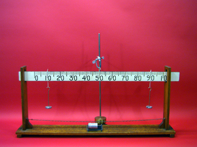
Meter Stick Torque Beam, 1J40.20
Topic and Concept:
Statistics of Rigid Bodies, 1J40. Static Torque
pira200 Listed
Location:
Cabinet: Mechanic (ME)
Bay: C1
Shelf: T
Abstract:
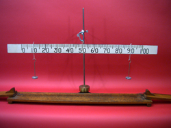
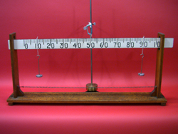
A meter stick, suspended at the center, is used as a torque balance. Different combinations of weights hung at different distances can keep the beam balanced demonstrating how torque works.
Equipment |
Location |
ID Number |
|
|
|
Torque Beam |
ME, Bay C1, Shelf T |
|
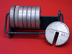
Weights and Weight Hangars |
|
|
3/4" Rod and clamps |
Rod and tackle cabinet near main lecture halls |
|
Important Setup Notes:
- N/A
Setup and Procedure:
- Place apparatus on lecture bench with numbered side facing audience.
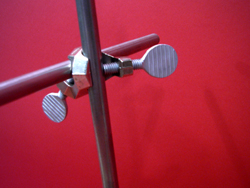
- Behind the apparatus, mount a 3/4" rod to the bench with a table clamp.
- To this vertical rod, attach another rod horizontally so that it is about above the apparatus, low enough so that the central loop of the beam can slip onto the rod (this is how we will suspend the beam).
- From each of the outer loops, hang a weight hangar, and load up each with some amount of weight.
- Choose the relative positions on the beam of the weights so that the beam will balance.
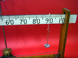
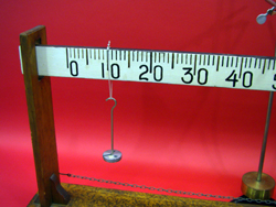
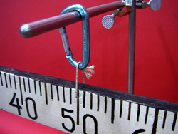
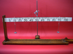
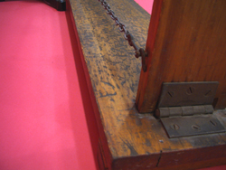
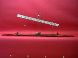
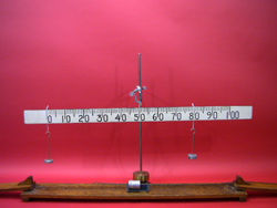
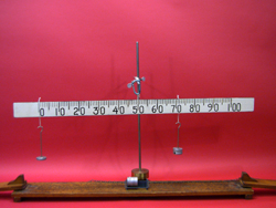
- The moment of truth: unhook the chain from the stage left leg of the apparatus. Push the legs out to free the beam. If the previous two steps were completed appropriately, the beam will remain balanced. See photos below for some examples of weight - position combinations.
Cautions, Warnings, or Safety Concerns:
- N/A
Discussion:
There are four torques acting on the beam: that due to gravity (weight of the beam), tension of the suspension string, and each of the two weights. If we set our origin at the 50 cm mark, the torque due to gravity and the tension go to zero. For the torques to balance giving us zero angular acceleration (keeping the beam balanced), we must have
r1·W1 = r2·W2 -> r1·m1 = r2·m2
where the r's denote the distance from the center of the beam of each weight hangar and the m's denote the total mass of the weight hangar.
|
|
|
|
|
|
|
|
|
|
|
|
Videos:
References:
