|
Size: 1257
Comment:
|
← Revision 4 as of 2013-07-12 18:17:57 ⇥
Size: 1686
Comment: converted to 1.6 markup
|
| Deletions are marked like this. | Additions are marked like this. |
| Line 2: | Line 2: |
| ||<:30%>[:PiraScheme#Mechanics: Table of Mechanics Demonstration]||<:30%>[:MEEquipmentList: List of Mechanics Equipment & Supplies]||<:30%>[:Demonstrations:Lecture Demonstrations]|| | ||<:30%>[[PiraScheme#WavesSound| Table of Waves & Sound Demonstration]]||<:30%>[[WSEquipmentList| List of Waves & Sound Equipment & Supplies]]||<:30%>[[Demonstrations|Lecture Demonstrations]]|| |
| Line 7: | Line 7: |
| * '''Cabinet:''' Waves and Sound (WS) * '''Bay:''' [:MechanicsCabinetBayA1:(A1)]?? * '''Shelf:''' #1,2,3.. ?? |
* '''Cabinet:''' [[EMCabinet| (E&M)]] * '''Bay:''' [[EMCabinetLtBayB1|(B1 Left)]] * '''Shelf:''' #2 |
| Line 11: | Line 11: |
| attachment:TuningForkOscilliscope14-400.jpg | {{attachment:TuningForkOscilliscope14-400.jpg}} |
| Line 22: | Line 22: |
| 1. List steps for setup then procedure. 1. ... |
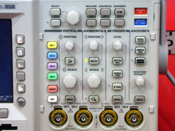
1. Plug in the oscilloscope. 1. Turn on the oscilloscope by pressing the power button located on the lower left-hand corner of the display side. 1. Plug in signal-carrying coaxial cable to channel 1. 1. Adjust scale by turning the horizontal and vertical scale knobs. 1. Adjust the position of the displayed waveform by turning the horizontal and vertical position knobs. 1. Adjust the trigger level by turning the trigger level knob. |
| Line 25: | Line 29: |
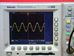
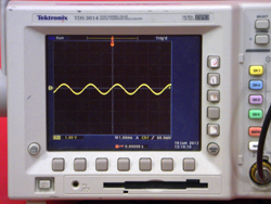
||attachment:TuningForkOscilliscope15-250.jpg||attachment:TuningForkOscilliscope16-250.jpg||attachment:TuningForkOscilliscope17-250.jpg||attachment:TuningForkOscilliscope19-250.jpg|| ||attachment:TuningForkOscilliscope20-250.jpg||attachment:TuningForkOscilliscope21-250.jpg|| |
||{{attachment:TuningForkOscilliscope15-250.jpg}}||{{attachment:TuningForkOscilliscope16-250.jpg}}||{{attachment:TuningForkOscilliscope17-250.jpg}}||{{attachment:TuningForkOscilliscope19-250.jpg}}|| ||{{attachment:TuningForkOscilliscope20-250.jpg}}||{{attachment:TuningForkOscilliscope21-250.jpg}}|| |
| Line 33: | Line 36: |
| * [https://en.wikipedia.org/wiki/Oscilloscope Wikipedia - Oscilloscope] * [https://en.wikipedia.org/wiki/Voltage Wikipedia - Voltage] |
* [[https://en.wikipedia.org/wiki/Oscilloscope|Wikipedia - Oscilloscope]] * [[https://en.wikipedia.org/wiki/Voltage|Wikipedia - Voltage]] |
| Line 37: | Line 40: |
| [:Instructional:Home] | [[Instructional|Home]] |
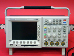
Tektronix TDS 3014 Four Channel Digital Oscilloscope
Location:
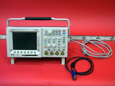
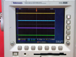
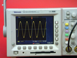
This device takes an electric signal (up to four at one time), processes it, and displays it in color in the form of a voltage versus time plot.
Important Setup Notes:
- N/A
Setup and Procedure:
- Plug in the oscilloscope.
- Turn on the oscilloscope by pressing the power button located on the lower left-hand corner of the display side.
- Plug in signal-carrying coaxial cable to channel 1.
- Adjust scale by turning the horizontal and vertical scale knobs.
- Adjust the position of the displayed waveform by turning the horizontal and vertical position knobs.
- Adjust the trigger level by turning the trigger level knob.
|
|
|
|
|
|
References:
