|
Size: 1609
Comment:
|
← Revision 7 as of 2013-07-12 18:18:11 ⇥
Size: 3740
Comment: converted to 1.6 markup
|
| Deletions are marked like this. | Additions are marked like this. |
| Line 2: | Line 2: |
| ||<:30%>[:PiraScheme#Mechanics: Table of Mechanics Demonstration]||<:30%>[:MEEquipmentList: List of Mechanics Equipment & Supplies]||<:30%>[:Demonstrations:Lecture Demonstrations]|| | ||<:30%>[[PiraScheme#Mechanics| Table of Mechanics Demonstration]]||<:30%>[[MEEquipmentList| List of Mechanics Equipment & Supplies]]||<:30%>[[Demonstrations|Lecture Demonstrations]]|| |
| Line 7: | Line 7: |
| Newton's First Law, [:Newtons1STLaw#InertiaofRest: 1F20. Inertia of Rest] | Rotational Dynamics, [[RotationalDynamics#Gyros| 1Q50. Gyroscopic Motion]] |
| Line 10: | Line 10: |
| * '''Cabinet:''' [:MechanicsCabinet:Mechanic (ME)] * '''Bay:''' [:MechanicsCabinetBayA12:(A12)] |
* '''Cabinet:''' [[MechanicsCabinet|Mechanic (ME)]] * '''Bay:''' [[MechanicsCabinetBayA12|(A12)]] |
| Line 14: | Line 14: |
| attachment: mainPhoto | {{attachment:MITACgyro06-400.jpg}} |
| Line 18: | Line 18: |
| Insert succinct description of demonstration. | A commercially built motorized gyro on a gimbal includes counterweights. |
| Line 22: | Line 22: |
| ||MITAC Gyroscope||[:MechanicsCabinetBayA12: ME, Bay A12, Shelf #1]|| || ||Weights||[:MechanicsCabinetBayA12: ME, Bay A12, Shelf #2]|| || |
||MITAC Gyroscope||[[MechanicsCabinetBayA12| ME, Bay A12, Shelf #1]]|| || ||Weights||[[MechanicsCabinetBayA12| ME, Bay A12, Shelf #1]]|| || |
| Line 27: | Line 27: |
| * '''''One of the three of our MITAC gyroscopes does not allow the outer ring to rotate around the vertical axis.''''' | * '''''One of the three of our MITAC gyroscopes does not allow the outer ring to rotate around the vertical axis.''''' * '''''It takes a few seconds for the flywheel to get up to speed.''''' |
| Line 32: | Line 33: |
| 1. List steps for setup then procedure. 1. ... |
1. Place the MITAC gyroscope on the table and unlock all the retaining screws that hold the rings in place. 1. Plug it in to a 110v outlet. 1. Weights can be added to either end of the Axle "arrow" (ie. Axes of rotation) to show precession and/or nutation. |
| Line 36: | Line 38: |
| * | * Keep fingers away from the moving parts of the gyroscope while it is running. |
| Line 41: | Line 43: |
| Discuss the physics behind the demonstration, explaining some of the various steps of the demonstration when appropriate. | Once the flywheel is at full speed, it now has angular momentum which is a conserved quantity provided that there exists no external torque on the flywheel's rotating axes. |
| Line 43: | Line 45: |
| ||attachment: photo||attachment: photo||attachment: photo||attachment: photo|| | When one tries to perturb the rotational motion of the flywheel by moving the outer most ring & base, azimuthal angle, the Axle "arrow" or axis of rotation of the flywheel tends to remain stationary. If one tries to move the central ring or the axle of the flywheel, this well cause the flywheel to wobble and rotate. This wobbling motion is a combination of two effects: nutation and precession. Nutation is essentially a wobble of the axis of rotation toward and away from the original axis. Precession is the rotation of the new axis of rotation around the original axis. These are shown in the graphic below. One can add a weight to the rotational axle of the flywheel to enhance the precession and nutation effects. ||{{attachment:MITACgyro01-250.jpg}}||{{attachment:MITACgyro02-250.jpg}}||{{attachment:MITACgyro03-250.jpg}}||{{attachment:MITACgyro04-250.jpg}}|| ||{{attachment:MITACgyro05-250.jpg}}||{{attachment:MITACgyro07-250.jpg}}||{{attachment:MITACgyro08-250.jpg}}||{{attachment:MITACgyro09-250.jpg}}|| ||{{attachment:MITACgyro10-250.jpg}}||{{attachment:MITACgyro11-250.jpg}}||{{attachment:MITACgyro12-250.jpg}}||{{attachment:MITACgyro13-250.jpg}}|| ||{{attachment:MITACgyro14-250.jpg}}||{{attachment:MITACgyro15-250.jpg}}||{{attachment:MITACgyro16-250.jpg}}||{{attachment:MITACgyro17-250.jpg}}|| ||{{attachment:MITACgyro18-250.jpg}}||{{attachment:MITACgyro19-250.jpg}}||{{attachment:MITACgyro20-250.jpg}}||{{attachment:precession_nutation-250.png}}|| |
| Line 46: | Line 54: |
| * [https://www.youtube.com/user/LectureDemostrations/videos?view=1 Lecture Demonstration's Youtube Channel] | * [[https://www.youtube.com/user/LectureDemostrations/videos?view=1|Lecture Demonstration's Youtube Channel]] |
| Line 50: | Line 58: |
| * List any references | * [[https://en.wikipedia.org/wiki/Gyroscope|Wikipedia - Gyroscope]] * [[https://en.wikipedia.org/wiki/Angular_momentum|Wikipedia - Angular Momentum]] * [[https://en.wikipedia.org/wiki/Nutation|Wikipedia - Nutation]] * [[https://en.wikipedia.org/wiki/Precession|Wikipedia - Precession]] |
| Line 53: | Line 64: |
| [:Instructional:Home] | [[Instructional|Home]] |
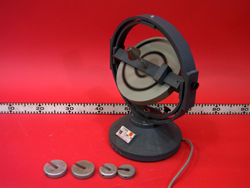
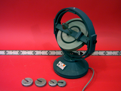
MITAC Gyroscope, 1Q50.30
Topic and Concept:
Rotational Dynamics, 1Q50. Gyroscopic Motion
Location:
Cabinet: Mechanic (ME)
Bay: (A12)
Shelf: #1
Abstract:
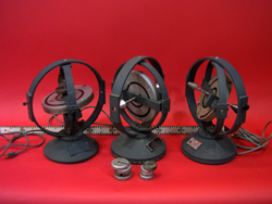
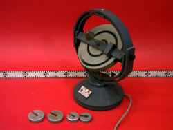
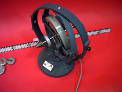
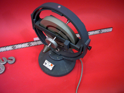
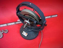
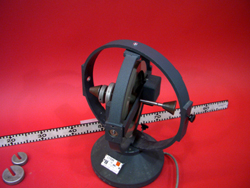
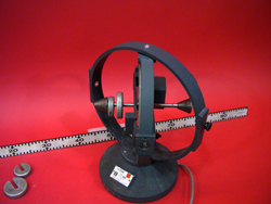
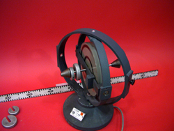
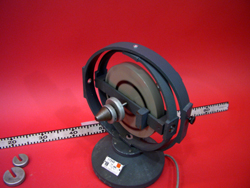
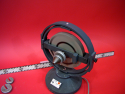
A commercially built motorized gyro on a gimbal includes counterweights.
Equipment |
Location |
ID Number |
|
|
|
MITAC Gyroscope |
|
|
Weights |
|
Important Setup Notes:
One of the three of our MITAC gyroscopes does not allow the outer ring to rotate around the vertical axis.
It takes a few seconds for the flywheel to get up to speed.
Setup and Procedure:
- Place the MITAC gyroscope on the table and unlock all the retaining screws that hold the rings in place.
- Plug it in to a 110v outlet.
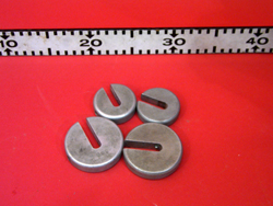
- Weights can be added to either end of the Axle "arrow" (ie. Axes of rotation) to show precession and/or nutation.
Cautions, Warnings, or Safety Concerns:
- Keep fingers away from the moving parts of the gyroscope while it is running.
Discussion:
Once the flywheel is at full speed, it now has angular momentum which is a conserved quantity provided that there exists no external torque on the flywheel's rotating axes.
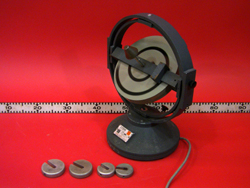
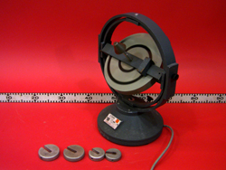
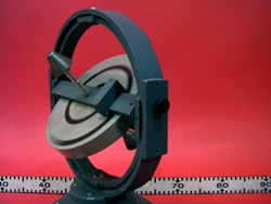
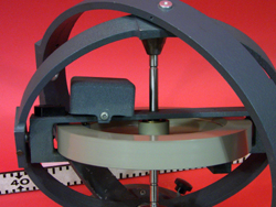
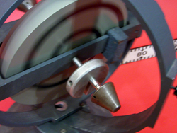
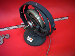
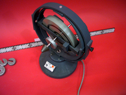
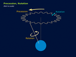
When one tries to perturb the rotational motion of the flywheel by moving the outer most ring & base, azimuthal angle, the Axle "arrow" or axis of rotation of the flywheel tends to remain stationary. If one tries to move the central ring or the axle of the flywheel, this well cause the flywheel to wobble and rotate. This wobbling motion is a combination of two effects: nutation and precession. Nutation is essentially a wobble of the axis of rotation toward and away from the original axis. Precession is the rotation of the new axis of rotation around the original axis. These are shown in the graphic below. One can add a weight to the rotational axle of the flywheel to enhance the precession and nutation effects.
|
|
|
|
|
|
|
|
|
|
|
|
|
|
|
|
|
|
|
|
Videos:
References:
