|
Size: 2432
Comment:
|
← Revision 16 as of 2019-12-11 22:12:56 ⇥
Size: 5465
Comment:
|
| Deletions are marked like this. | Additions are marked like this. |
| Line 2: | Line 2: |
| ||<:30%>[:PiraScheme#Mechanics: Table of Mechanics Demonstration]||<:30%>[:MEEquipmentList: List of Mechanics Equipment & Supplies]||<:30%>[:Demonstrations:Lecture Demonstrations]|| | ||<30% style="" & quot;text-align:center& quot; " ">[[PiraScheme#WavesSound|Table of Waves and Sound Demonstration]] ||<30% style="" & quot;text-align:center& quot; " ">[[MEEquipmentList|List of Mechanics Equipment & Supplies]] ||<30% style="" & quot;text-align:center& quot; " ">[[Demonstrations|Lecture Demonstrations]] || |
| Line 5: | Line 6: |
| '''Topic and Concept:''' | |
| Line 6: | Line 8: |
| '''Topic and Concept:''' Oscillations, [:Oscillations#DrivenRes: 3A60. Driven Mechanical Resonance] |
. Oscillations, [[Oscillations#DrivenRes|3A60. Driven Mechanical Resonance]] |
| Line 10: | Line 11: |
| * '''Cabinet:''' [:MechanicsCabinet:Mechanic (ME)] * '''Bay:''' [:MechanicsCabinetBayA1:(A1)] * '''Shelf:''' #1,2,3.. |
|
| Line 14: | Line 12: |
| attachment:DrivenMassSpring18-400.jpg | * '''Cabinet:''' [[WavesSoundCabinet|Waves and Sound (WS)]] * '''Bay:''' [[WSCabinetRtBayA4|(A4 Right)]] * '''Shelf:''' #1 {{attachment:DrivenMassSpring18-400.jpg}} |
| Line 19: | Line 21: |
||<:style="width: 60%" :40%>'''Equipment'''||<:30%>'''Location'''||<:25%>'''ID Number'''|| |
||<40% style="" & quot; & amp; quot; ;text-align:center& quot; " ">'''Equipment''' ||<30% style="" & quot;text-align:center& quot; " ">'''Location''' ||<25% style="" & quot;text-align:center& quot; " ">'''ID Number''' || |
| Line 22: | Line 23: |
| ||Function Generator||[:MechanicsCabinetBayB1: ME, Bay B1, Shelf #2]|| || ||Pasco Driver||[:MechanicsCabinetBayB1: ME, Bay B1, Shelf #2]|| || ||BNC Wire||[:MechanicsCabinetBayA5: ME, Bay A5, Shelf #2]|| || |
||Function Generator ||[[EMCabinetLtBayB1|EM, Bay B1 Left, Shelf #3]] || || ||Pasco Driver ||[[WSCabinetRtBayA4|WS, Bay A4, Shelf #2]] || || ||Coaxial Cable ||Rod and tackle cabinet located near main lecture halls || || ||Springs ||[[WSCabinetRtBayA4|WS, Bay A4, Shelf #2]] || || ||100g Mass ||[[MechanicsCabinetBayA1|ME, Bay A1, Shelf #5]] || || ||Rod and Clamps ||Rod and tackle cabinet located near main lecture halls || || |
| Line 27: | Line 31: |
| '''''Important Setup Notes:''''' * Demonstration may require practice. |
|
| Line 31: | Line 33: |
| '''Setup and Procedure:''' | '''''Important Setup Notes:''''' |
| Line 33: | Line 35: |
| 1. List steps for setup then procedure. 1. ... |
* Demonstration may require practice. '''Setup and Procedure:''' 1. Vertically mount 3/4" rod to lecture bench using blue table clamp. 1. Horizontally mount 1/4" rod to the vertical rod using a right angle clamp. 1. Mount the Pasco driver to the 1/4" rod so that the driving component will move in a vertical direction. 1. Place the function generator on the table near the rod, and plug it in. 1. Connect the driver to the function generator with the two wires. Positive to positive. Ground to ground. 1. Find the shorter of the two springs near the Pasco Drivers that has a banana connector soldered onto one end (see picture below). Hang the spring from the driver. 1. Hang the 100g mass from the spring. 1. When ready, turn on the function generator by pressing the "On" button. 1. The mass will begin to oscillate in a vertical direction. Adjust the frequency of oscillation by changing the driving frequency set on the function generator so that the system approaches resonance (some practice beforehand is recommended). On 12/12/19, resonance frequency was found to be about 1. 0.797 Hz, and resonance amplitude was about 30 cm (ie 60 cm peak to peak). |
| Line 37: | Line 51: |
| Line 39: | Line 54: |
| '''Discussion:''' | |
| Line 40: | Line 56: |
| '''Discussion:''' | The dynamics of this system are described by a linear, inhomogeneous, second order, 2D (one spatial dimension, one time dimension) differential equation (see [[http://hyperphysics.phy-astr.gsu.edu/hbase/oscdr.html|Hyperphysics- Driven Oscillator]]). The inhomogeneous part comes from the driving force which is sinusoidal having a general form of |
| Line 42: | Line 58: |
| Discuss the physics behind the demonstration, explaining some of the various steps of the demonstration when appropriate. | F(t) = F,,0,, * cos(ω*t - φ,,d,,) |
| Line 44: | Line 60: |
| ||attachment:DrivenMassSpring13-250.jpg||attachment:DrivenMassSpring14-250.jpg||attachment:DrivenMassSpring15-250.jpg||attachment:DrivenMassSpring16-250.jpg|| ||attachment:DrivenMassSpring17-250.jpg||attachment:DrivenMassSpring19-250.jpg||attachment:DrivenMassSpring20-250.jpg||attachment:DrivenMassSpring21-250.jpg|| ||attachment:DrivenMassSpring22-250.jpg||attachment:DrivenMassSpring23-250.jpg||attachment:DrivenMassSpring24-250.jpg||attachment:DrivenMassSpring25-250.jpg|| ||attachment:DrivenMassSpring26-250.jpg||attachment:DrivenMassSpring27-250.jpg||attachment:DrivenMassSpring28-250.jpg|| ||attachment:DrivenMassSpring29-250.jpg||attachment:DrivenMassSpring30-250.jpg|| |
where F,,0,, is the driving amplitude, ω is the driving frequency, and φ,,d,, is the phase angle. F,,0,, and ω are set on the function generator. The steady-state solution (letting t go to infinity) has the form x(t) = A*cos(ω*t - φ) where A, and φ depend on the specifics of the driving force, the spring constant, damping, and the mass used. After more math, we find that A has the form A = (F,,0,,/m) / Sqrt((ω^2^-ω,,0,,^2^)^2^ + 4*γ^2^*ω^2^) where m is the mass, γ encodes the damping information, and ω,,0,, = Sqrt(k/m), k being the spring constant. Since the only variable in our expression for A is ω (we're only varying the driving frequency ω), A will be at a maximum when we minimize the denominator. This gives us ω,,resonance,, = Sqrt(ω,,0,,^2^ - 2*γ^2^). We call this value of ω the resonant frequency of the system. || {{attachment:DrivenMassSpring13-250.jpg}} || {{attachment:DrivenMassSpring14-250.jpg}} || {{attachment:DrivenMassSpring15-250.jpg}} || {{attachment:DrivenMassSpring16-250.jpg}} || || {{attachment:DrivenMassSpring17-250.jpg}} || {{attachment:DrivenMassSpring19-250.jpg}} || {{attachment:DrivenMassSpring20-250.jpg}} || {{attachment:DrivenMassSpring21-250.jpg}} || || {{attachment:DrivenMassSpring22-250.jpg}} || {{attachment:DrivenMassSpring23-250.jpg}} || {{attachment:DrivenMassSpring24-250.jpg}} || {{attachment:DrivenMassSpring25-250.jpg}} || || {{attachment:DrivenMassSpring26-250.jpg}} || {{attachment:DrivenMassSpring27-250.jpg}} || {{attachment:DrivenMassSpring28-250.jpg}} || {{attachment:DrivenMassSpring29-250.jpg}} || || {{attachment:DrivenMassSpring30-250.jpg}} || |
| Line 51: | Line 77: |
| * [https://www.youtube.com/user/LectureDemostrations/videos?view=1 Lecture Demonstration's Youtube Channel] | * [[https://www.youtube.com/user/LectureDemostrations/videos?view=1|Lecture Demonstration's Youtube Channel]] |
| Line 55: | Line 82: |
| * [https://en.wikipedia.org/wiki/Harmonic_oscillator Wikipedia - Harmonic Oscillator] * [https://en.wikipedia.org/wiki/Resonance Wikipedia - Resonance] |
* [[https://en.wikipedia.org/wiki/Harmonic_oscillator|Wikipedia - Harmonic Oscillator]] * [[https://en.wikipedia.org/wiki/Resonance|Wikipedia - Resonance]] * [[http://hyperphysics.phy-astr.gsu.edu/hbase/oscdr.html|Hyperphysics- Driven Oscillator]] |
| Line 58: | Line 86: |
[:Instructional:Home] |
[[Instructional|Home]] |
Driven Mass on a Spring, 3A60.39
Topic and Concept:
Oscillations, 3A60. Driven Mechanical Resonance
Location:
Cabinet: Waves and Sound (WS)
Bay: (A4 Right)
Shelf: #1
Abstract:
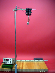
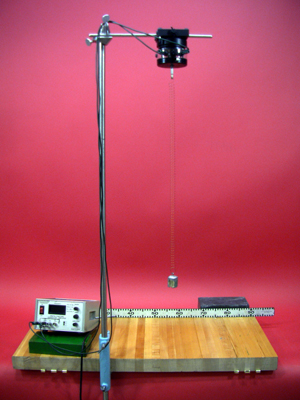
A function generator drives a spring with a suspended mass. The frequency is adjusted until resonance is reached.
Equipment |
Location |
ID Number |
|
|
|
Function Generator |
|
|
Pasco Driver |
|
|
Coaxial Cable |
Rod and tackle cabinet located near main lecture halls |
|
Springs |
|
|
100g Mass |
|
|
Rod and Clamps |
Rod and tackle cabinet located near main lecture halls |
|
Important Setup Notes:
- Demonstration may require practice.
Setup and Procedure:
- Vertically mount 3/4" rod to lecture bench using blue table clamp.
- Horizontally mount 1/4" rod to the vertical rod using a right angle clamp.
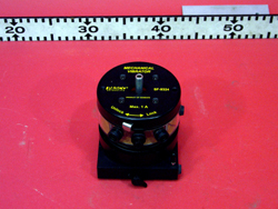
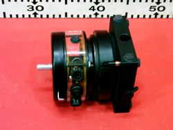
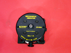
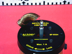
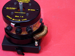
- Mount the Pasco driver to the 1/4" rod so that the driving component will move in a vertical direction.
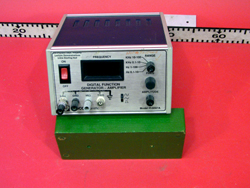
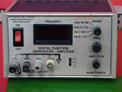
- Place the function generator on the table near the rod, and plug it in.
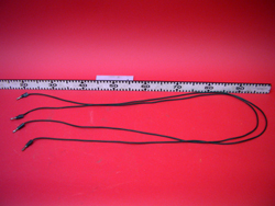
- Connect the driver to the function generator with the two wires. Positive to positive. Ground to ground.
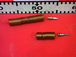
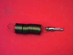
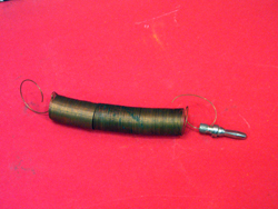
- Find the shorter of the two springs near the Pasco Drivers that has a banana connector soldered onto one end (see picture below). Hang the spring from the driver.
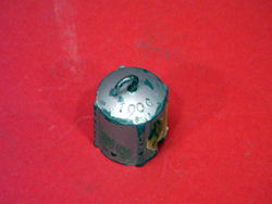
- Hang the 100g mass from the spring.
- When ready, turn on the function generator by pressing the "On" button.
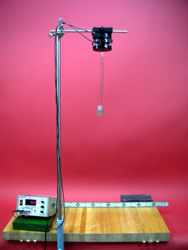
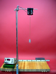
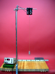
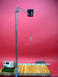
- The mass will begin to oscillate in a vertical direction. Adjust the frequency of oscillation by changing the driving frequency set on the function generator so that the system approaches resonance (some practice beforehand is recommended). On 12/12/19, resonance frequency was found to be about
- 0.797 Hz, and resonance amplitude was about 30 cm (ie 60 cm peak to peak).
Cautions, Warnings, or Safety Concerns:
- N/A
Discussion:
The dynamics of this system are described by a linear, inhomogeneous, second order, 2D (one spatial dimension, one time dimension) differential equation (see Hyperphysics- Driven Oscillator). The inhomogeneous part comes from the driving force which is sinusoidal having a general form of
F(t) = F0 * cos(ω*t - φd)
where F0 is the driving amplitude, ω is the driving frequency, and φd is the phase angle. F0 and ω are set on the function generator. The steady-state solution (letting t go to infinity) has the form
x(t) = A*cos(ω*t - φ) where A, and φ depend on the specifics of the driving force, the spring constant, damping, and the mass used. After more math, we find that A has the form
A = (F0/m) / Sqrt((ω2-ω02)2 + 4*γ2*ω2)
where m is the mass, γ encodes the damping information, and ω0 = Sqrt(k/m), k being the spring constant. Since the only variable in our expression for A is ω (we're only varying the driving frequency ω), A will be at a maximum when we minimize the denominator. This gives us ωresonance = Sqrt(ω02 - 2*γ2). We call this value of ω the resonant frequency of the system.
|
|
|
|
|
|
|
|
|
|
|
|
|
|
|
|
|
Videos:
References:
