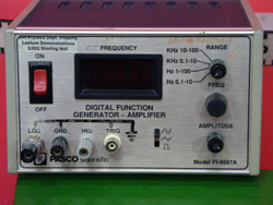
|
Size: 4751
Comment: converted to 1.6 markup
|
← Revision 16 as of 2019-12-11 22:12:56 ⇥
Size: 5465
Comment:
|
| Deletions are marked like this. | Additions are marked like this. |
| Line 2: | Line 2: |
| ||<:30%>[[PiraScheme#WavesSound| Table of Waves and Sound Demonstration]]||<:30%>[[MEEquipmentList| List of Mechanics Equipment & Supplies]]||<:30%>[[Demonstrations|Lecture Demonstrations]]|| | ||<30% style="" & quot;text-align:center& quot; " ">[[PiraScheme#WavesSound|Table of Waves and Sound Demonstration]] ||<30% style="" & quot;text-align:center& quot; " ">[[MEEquipmentList|List of Mechanics Equipment & Supplies]] ||<30% style="" & quot;text-align:center& quot; " ">[[Demonstrations|Lecture Demonstrations]] || |
| Line 5: | Line 6: |
| '''Topic and Concept:''' | |
| Line 6: | Line 8: |
| '''Topic and Concept:''' Oscillations, [[Oscillations#DrivenRes| 3A60. Driven Mechanical Resonance]] |
. Oscillations, [[Oscillations#DrivenRes|3A60. Driven Mechanical Resonance]] |
| Line 10: | Line 11: |
| * '''Cabinet:''' [[WavesSoundCabinet| Waves and Sound (WS)]] | * '''Cabinet:''' [[WavesSoundCabinet|Waves and Sound (WS)]] |
| Line 19: | Line 21: |
||<:style="width: 60%" :40%>'''Equipment'''||<:30%>'''Location'''||<:25%>'''ID Number'''|| |
||<40% style="" & quot; & amp; quot; ;text-align:center& quot; " ">'''Equipment''' ||<30% style="" & quot;text-align:center& quot; " ">'''Location''' ||<25% style="" & quot;text-align:center& quot; " ">'''ID Number''' || |
| Line 22: | Line 23: |
| ||Function Generator||[[EMCabinetLtBayB1| EM, Bay B1 Left, Shelf #3]]|| || ||Pasco Driver||[[WSCabinetRtBayA4| WS, Bay A4, Shelf #2]]|| || ||Coaxial Cable||Rod and tackle cabinet located near main lecture halls|| || ||Springs||[[WSCabinetRtBayA4| WS, Bay A4, Shelf #2]]|| || ||Mass||[[MechanicsCabinetBayA1| ME, Bay A1, Shelf #5]]|| || ||Rod and Clamps||Rod and tackle cabinet located near main lecture halls|| || |
||Function Generator ||[[EMCabinetLtBayB1|EM, Bay B1 Left, Shelf #3]] || || ||Pasco Driver ||[[WSCabinetRtBayA4|WS, Bay A4, Shelf #2]] || || ||Coaxial Cable ||Rod and tackle cabinet located near main lecture halls || || ||Springs ||[[WSCabinetRtBayA4|WS, Bay A4, Shelf #2]] || || ||100g Mass ||[[MechanicsCabinetBayA1|ME, Bay A1, Shelf #5]] || || ||Rod and Clamps ||Rod and tackle cabinet located near main lecture halls || || |
| Line 30: | Line 31: |
| '''''Important Setup Notes:''''' * Demonstration may require practice. |
|
| Line 34: | Line 33: |
| '''Setup and Procedure:''' | '''''Important Setup Notes:''''' * Demonstration may require practice. '''Setup and Procedure:''' |
| Line 41: | Line 44: |
| 1. Hang the spring from the driver. 1. Hang the mass from the spring. |
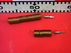
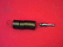
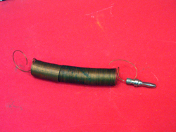
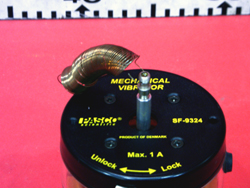
1. Find the shorter of the two springs near the Pasco Drivers that has a banana connector soldered onto one end (see picture below). Hang the spring from the driver. 1. Hang the 100g mass from the spring. |
| Line 44: | Line 47: |
| 1. The mass will begin to oscillate in a vertical direction. Adjust the frequency of oscillation by changing the driving frequency set on the function generator so that the system approaches resonance (some practice beforehand is recommended). | 1. The mass will begin to oscillate in a vertical direction. Adjust the frequency of oscillation by changing the driving frequency set on the function generator so that the system approaches resonance (some practice beforehand is recommended). On 12/12/19, resonance frequency was found to be about 1. 0.797 Hz, and resonance amplitude was about 30 cm (ie 60 cm peak to peak). |
| Line 47: | Line 51: |
| Line 49: | Line 54: |
'''Discussion:''' |
'''Discussion:''' |
| Line 56: | Line 60: |
| where F,,0,, is the driving amplitude, ω is the driving frequency, and φ,,d,, is the phase angle. F,,0,, and ω are set on the function generator. The steady-state solution (letting t go to infinity) has the form |
where F,,0,, is the driving amplitude, ω is the driving frequency, and φ,,d,, is the phase angle. F,,0,, and ω are set on the function generator. The steady-state solution (letting t go to infinity) has the form |
| Line 64: | Line 67: |
| || {{attachment:DrivenMassSpring13-250.jpg}} || {{attachment:DrivenMassSpring14-250.jpg}} || {{attachment:DrivenMassSpring15-250.jpg}} || {{attachment:DrivenMassSpring16-250.jpg}} || || {{attachment:DrivenMassSpring17-250.jpg}} || {{attachment:DrivenMassSpring19-250.jpg}} || {{attachment:DrivenMassSpring20-250.jpg}} || {{attachment:DrivenMassSpring21-250.jpg}} || || {{attachment:DrivenMassSpring22-250.jpg}} || {{attachment:DrivenMassSpring23-250.jpg}} || {{attachment:DrivenMassSpring24-250.jpg}} || {{attachment:DrivenMassSpring25-250.jpg}} || || {{attachment:DrivenMassSpring26-250.jpg}} || {{attachment:DrivenMassSpring27-250.jpg}} || {{attachment:DrivenMassSpring28-250.jpg}} || {{attachment:DrivenMassSpring29-250.jpg}} || || {{attachment:DrivenMassSpring30-250.jpg}} || |
|
| Line 65: | Line 73: |
| ||{{attachment:DrivenMassSpring13-250.jpg}}||{{attachment:DrivenMassSpring14-250.jpg}}||{{attachment:DrivenMassSpring15-250.jpg}}||{{attachment:DrivenMassSpring16-250.jpg}}|| ||{{attachment:DrivenMassSpring17-250.jpg}}||{{attachment:DrivenMassSpring19-250.jpg}}||{{attachment:DrivenMassSpring20-250.jpg}}||{{attachment:DrivenMassSpring21-250.jpg}}|| ||{{attachment:DrivenMassSpring22-250.jpg}}||{{attachment:DrivenMassSpring23-250.jpg}}||{{attachment:DrivenMassSpring24-250.jpg}}||{{attachment:DrivenMassSpring25-250.jpg}}|| ||{{attachment:DrivenMassSpring26-250.jpg}}||{{attachment:DrivenMassSpring27-250.jpg}}||{{attachment:DrivenMassSpring28-250.jpg}}||{{attachment:DrivenMassSpring29-250.jpg}}|| ||{{attachment:DrivenMassSpring30-250.jpg}}|| |
|
| Line 72: | Line 77: |
| Line 80: | Line 86: |
Driven Mass on a Spring, 3A60.39
Topic and Concept:
Oscillations, 3A60. Driven Mechanical Resonance
Location:
Cabinet: Waves and Sound (WS)
Bay: (A4 Right)
Shelf: #1
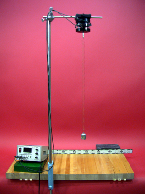
Abstract:
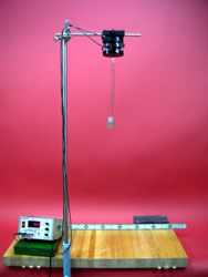
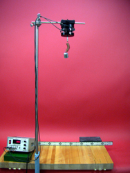
A function generator drives a spring with a suspended mass. The frequency is adjusted until resonance is reached.
Equipment |
Location |
ID Number |
|
|
|
Function Generator |
|
|
Pasco Driver |
|
|
Coaxial Cable |
Rod and tackle cabinet located near main lecture halls |
|
Springs |
|
|
100g Mass |
|
|
Rod and Clamps |
Rod and tackle cabinet located near main lecture halls |
|
Important Setup Notes:
- Demonstration may require practice.
Setup and Procedure:
- Vertically mount 3/4" rod to lecture bench using blue table clamp.
- Horizontally mount 1/4" rod to the vertical rod using a right angle clamp.
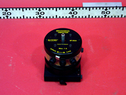
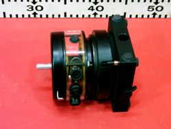
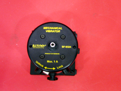
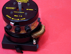
- Mount the Pasco driver to the 1/4" rod so that the driving component will move in a vertical direction.
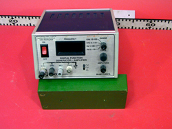
- Place the function generator on the table near the rod, and plug it in.
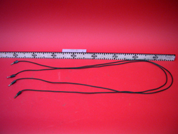
- Connect the driver to the function generator with the two wires. Positive to positive. Ground to ground.
- Find the shorter of the two springs near the Pasco Drivers that has a banana connector soldered onto one end (see picture below). Hang the spring from the driver.
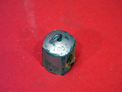
- Hang the 100g mass from the spring.
- When ready, turn on the function generator by pressing the "On" button.
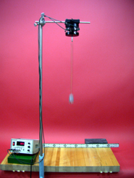
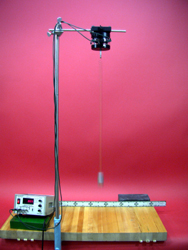
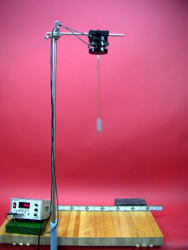
- The mass will begin to oscillate in a vertical direction. Adjust the frequency of oscillation by changing the driving frequency set on the function generator so that the system approaches resonance (some practice beforehand is recommended). On 12/12/19, resonance frequency was found to be about
- 0.797 Hz, and resonance amplitude was about 30 cm (ie 60 cm peak to peak).
Cautions, Warnings, or Safety Concerns:
- N/A
Discussion:
The dynamics of this system are described by a linear, inhomogeneous, second order, 2D (one spatial dimension, one time dimension) differential equation (see Hyperphysics- Driven Oscillator). The inhomogeneous part comes from the driving force which is sinusoidal having a general form of
F(t) = F0 * cos(ω*t - φd)
where F0 is the driving amplitude, ω is the driving frequency, and φd is the phase angle. F0 and ω are set on the function generator. The steady-state solution (letting t go to infinity) has the form
x(t) = A*cos(ω*t - φ) where A, and φ depend on the specifics of the driving force, the spring constant, damping, and the mass used. After more math, we find that A has the form
A = (F0/m) / Sqrt((ω2-ω02)2 + 4*γ2*ω2)
where m is the mass, γ encodes the damping information, and ω0 = Sqrt(k/m), k being the spring constant. Since the only variable in our expression for A is ω (we're only varying the driving frequency ω), A will be at a maximum when we minimize the denominator. This gives us ωresonance = Sqrt(ω02 - 2*γ2). We call this value of ω the resonant frequency of the system.
|
|
|
|
|
|
|
|
|
|
|
|
|
|
|
|
|
Videos:
References:
