|
Size: 2909
Comment:
|
Size: 2859
Comment: converted to 1.6 markup
|
| Deletions are marked like this. | Additions are marked like this. |
| Line 4: | Line 4: |
| attachment:ChargeDistributionSpheres5B3020.jpg | {{attachment:ChargeDistributionSpheres5B3020.jpg}} |
| Line 6: | Line 6: |
| The two conducting spheres, the Faraday cage, the electrometer, and the 1000V power supply (if needed) are in the [:ElectrostaticsCabinet:ElectrostaticsCabinet], B1. | The two conducting spheres, the Faraday cage, the electrometer, and the 1000V power supply (if needed) are in the [[ElectrostaticsCabinet]], B1. |
| Line 8: | Line 8: |
| The fur and proof plane are in the [:ElectrostaticsCabinet:ElectrostaticsCabinet], A1. | The fur and proof plane are in the [[ElectrostaticsCabinet]], A1. |
| Line 55: | Line 55: |
| [:ElectricFieldsAndPotential:Electric Fields and Potential] | [[ElectricFieldsAndPotential|Electric Fields and Potential]] |
| Line 57: | Line 57: |
| [:Demonstrations:Demonstrations] | [[Demonstrations]] |
| Line 59: | Line 59: |
| [:Instructional:Home] | [[Instructional|Home]] |
Charge Distribution on Conducting Spheres 5B30.20

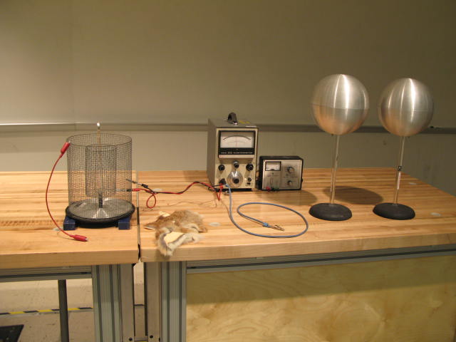
The two conducting spheres, the Faraday cage, the electrometer, and the 1000V power supply (if needed) are in the ElectrostaticsCabinet, B1.
The fur and proof plane are in the ElectrostaticsCabinet, A1.
Connect the Faraday cage to the electrometer, grounding the outside cage.
Set the electrometer to center zero, and 30V scale.
Connect one of the conducting spheres to ground. Move the other far away.
Discharge the proof plane.
Verify the proof plane is uncharged by brining it near the inner Faraday cage, and seeing that the needle does not deflect.
Preliminaries:
- Lay the proof plane against one side of the conducting sphere, then touch it to the inner Faraday cage. The needle should not deflect.
- Repeat for the other side of the conducting sphere. The needle should again not deflect.
- This establishes that the conducting sphere is not only grounded, but also has a zero charge density on both sides.
- Remove the ground wire from the conducting sphere, and repeat the two steps above. The results should be the same. Now the sphere is floating, but uncharged, and still has zero charge density on both sides.
Here is the experiment:
- place the second sphere about 1 m from the first. Rub the fur on it. It will acquire a charge (probably negative).
- lay the proof plane against either side of the second sphere, then touch it to the inner Faraday cage. The needle should deflect. This verifies the second sphere is charged. Note the sign of the charge.
- Zero the meter.
- place the second sphere about 10 cm from the first.
- Repeat the measurements of the charge density on both sides of the uncharged sphere that were done during "preliminaries", above. There should now be opposite and roughly equal charge densities on the two sides, with the sign of the charge on the side nearest the charged sphere being opposite to the sign of the charge on the charged sphere.
There are many variations of this experiment that can be done.
Notes:
On damp days, use the 1000V power supply rather than the fur to charge the second sphere.
If the inner Faraday cage retains a charge, discharge it by shorting it to the outer cage. Try doing this using a. your finger; or b. a wire with clip leads on both ends. Use whichever method leaves the needle closer to zero after you move your hand away from the inner cage.
Keep both spheres as far as practical from the Faraday cage and electrometer.
Make sure the leads to the electrometer are twisted.